Chapters 4,5,6,7 - Fuselage Structure and
|
|
|
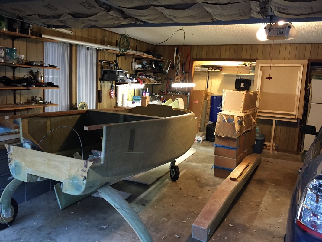
After ordering materials for Chapters 4-8 to do the fuselage, I diverted and bought David Pierce's project. His fuselage was in very good shape and here, I'll focus on the few things I did once I'd received it.
A short note to new builders who might be visiting this site: I traced the drawing for the instrument panel by taping it to sliding glass door which was great for tracing, but I was not happy with the mirroring of the original drawings and so I went to the online CAD drawings (see cozybuilders.org/CAD files) and got help from Adam Bryant plotting the full sized CAD drawings. I spent an inordinate amount of time checking the CAD with the paper drawings because they appear slightly smaller in the lateral dimension than the paper. I queried the builders and several folks had build with the CAD with no problems (you just have to check and make sure they are true to the digital scale in both directions as explained in the readme.txt).
A short note to new builders who might be visiting this site: I traced the drawing for the instrument panel by taping it to sliding glass door which was great for tracing, but I was not happy with the mirroring of the original drawings and so I went to the online CAD drawings (see cozybuilders.org/CAD files) and got help from Adam Bryant plotting the full sized CAD drawings. I spent an inordinate amount of time checking the CAD with the paper drawings because they appear slightly smaller in the lateral dimension than the paper. I queried the builders and several folks had build with the CAD with no problems (you just have to check and make sure they are true to the digital scale in both directions as explained in the readme.txt).
Inspection:
|
I examined the fuselage even more thoroughly when I got it home from Florida and over a couple of months of working on it as described below. The layups look very good and though it's impossible to measure their thickness in the areas where many layers are installed, I have compared what I have with what I see on other builders I've visited and combined with David Pierce's conscientious attitude and the condition of his workspace and workbench (big/heavy/flat) I'm very comfortable that his use of all the prescribed layups in the build from FG-30 back to the lower firewall are very good. I found only three things of note that I need to deal with on the fuselage going forward and they are addressed in this portion of the website:
a) Main Langing Gear Cover not smooth with bottom and NACA Scoop b) Landing brake is not smooth with bottom c) the lateral alignment of NG-30 is off by 1/2 degree forward of F-20 |
Main Landing Gear Cover: Ch 9 Step 4
|
Unfortunately I don't have a good picture of the landing gear cover as received. It's one of those picture taking habits that I needed to develop for documenting work. However, I have lots of pictures after I started working on it. I decided that it was fundamentally sound, but that it just didn't fit well to the fuselage and had lips all around that did not allow for good flow both over the bottom and internal to the NACA scoop. It's one of the first things I started working on (along with the landing brake and in this case, the only great thing about starting with it was that it provided a lot of opportunity to learn about complex shaping/attaching while working on a piece that if I failed at it, I could just build another from scratch. I'm happy with the result, but may find that after the plane is flying, I come back to this as an improvement area once I'm MUCH more experienced. So here's what I did:
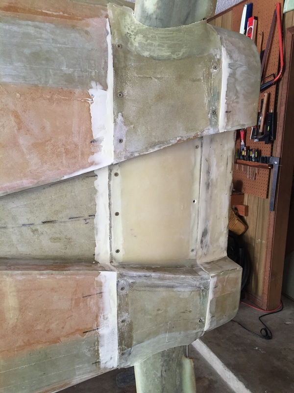
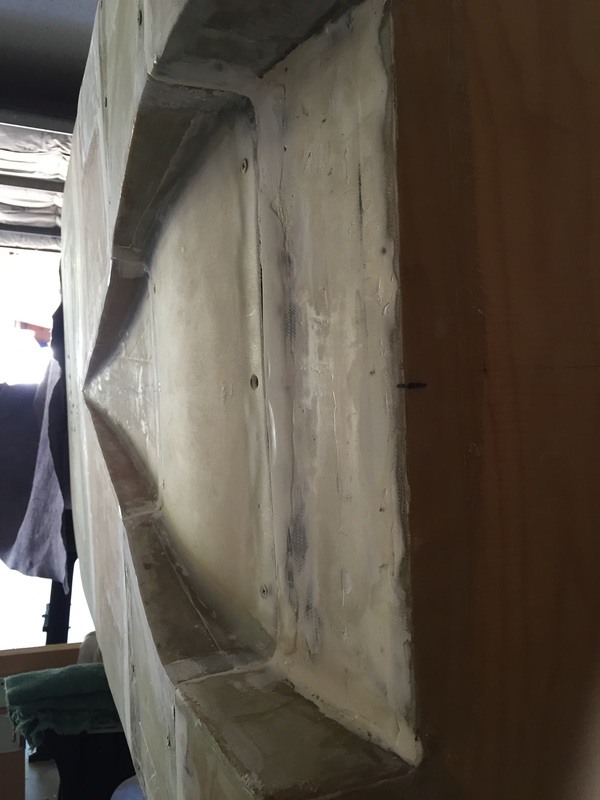
First I wanted to address the bottom of the NACA scoop. There was a big lip and poor corners in the scoop and the back side reinforcement was not the 3/8" PVC foam, but 2 strips of 1" thick Eurethane foam, shaped to go around the main gear bow strut. I dealt with this by trimming down the earthen to 3/8", and faring in a curved surface on the duct side that allowed a smooth transition from the angle of the duct coming into that point and going out the back. This allowed me to have a sandwich structure with 2 layers of BID on both sides, while smoothing this flow transition area. The maximum thickness of the faired foam was less than 1/4". I also floxed and glassed the forward and aft edges of the side "wings" of this piece along with doing some micro based fairing of the fuselage where there were local dips . This strengthened the mounting holes as well. Finally, I built up a clay mold around the main gear strut on both sides and played up 2 layers of BID to make a better transition to this piece on both sides. This closed some very large gaps between the gear legs and the cover, while leaving some room for flex in the legs. This required A LOT of iterations, because I was learning. Too many to list here. I tried some different foams. I applied micro and ended up sanding it all off, I worked with peel ply in curved surfaces for the first time. I used weights and such to hold parts in position against other parts. I got used to flox of different consistencies. I practiced using pallet wrap to mask off areas and interface with the clay form. The bottom line is that I spent a lot more time on this piece than an expert would. That's OK because I wanted this experience before moving to more significantly loaded parts.
|
Landing Brake (Ch 9 Step 8)
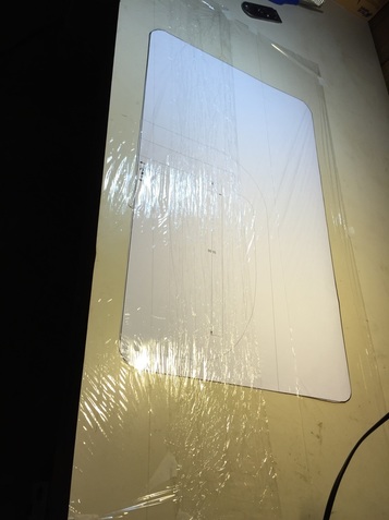
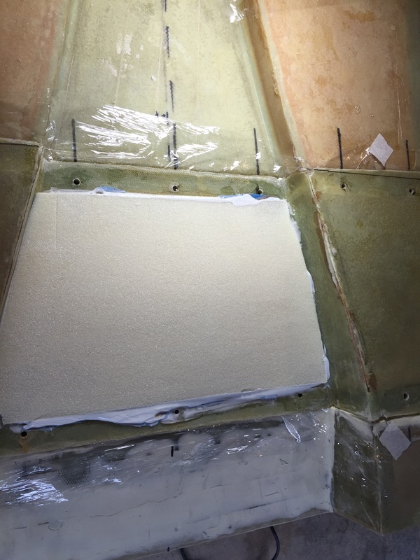
landing Brake pattern on bench under bottom pallet wrap before layup start
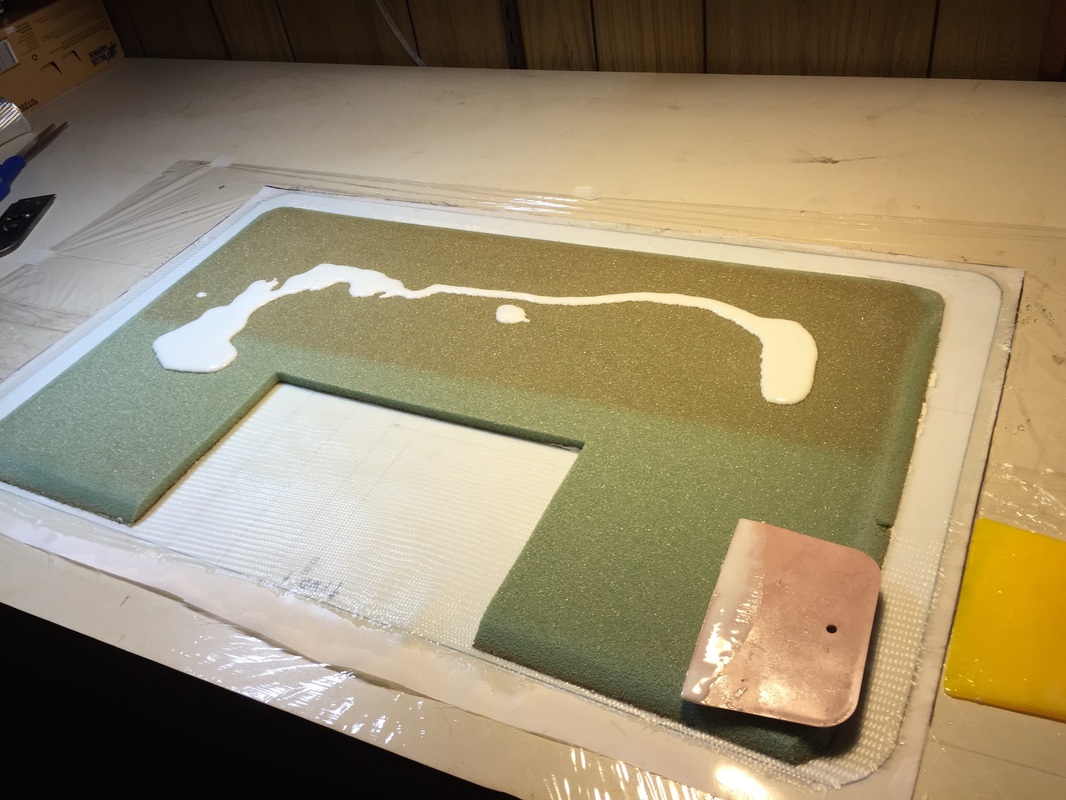
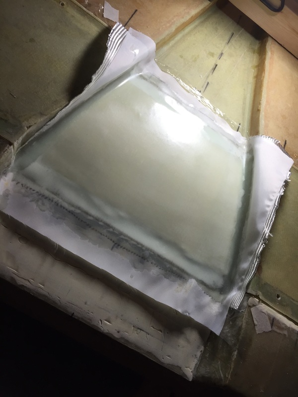
1/2 way through the layup micro'ing what will be the bottom side of the foam when installed...
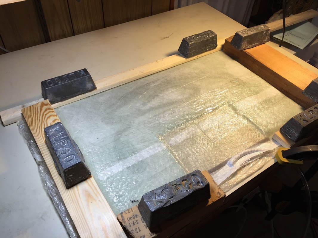
Vacuum applied to complete layup. Edge flanges weighted flat. Paper towels under pallet wrap are absorbing excess epoxy through the peel ply layer. This early cure on bench was 2.5 hrs then knife trim.
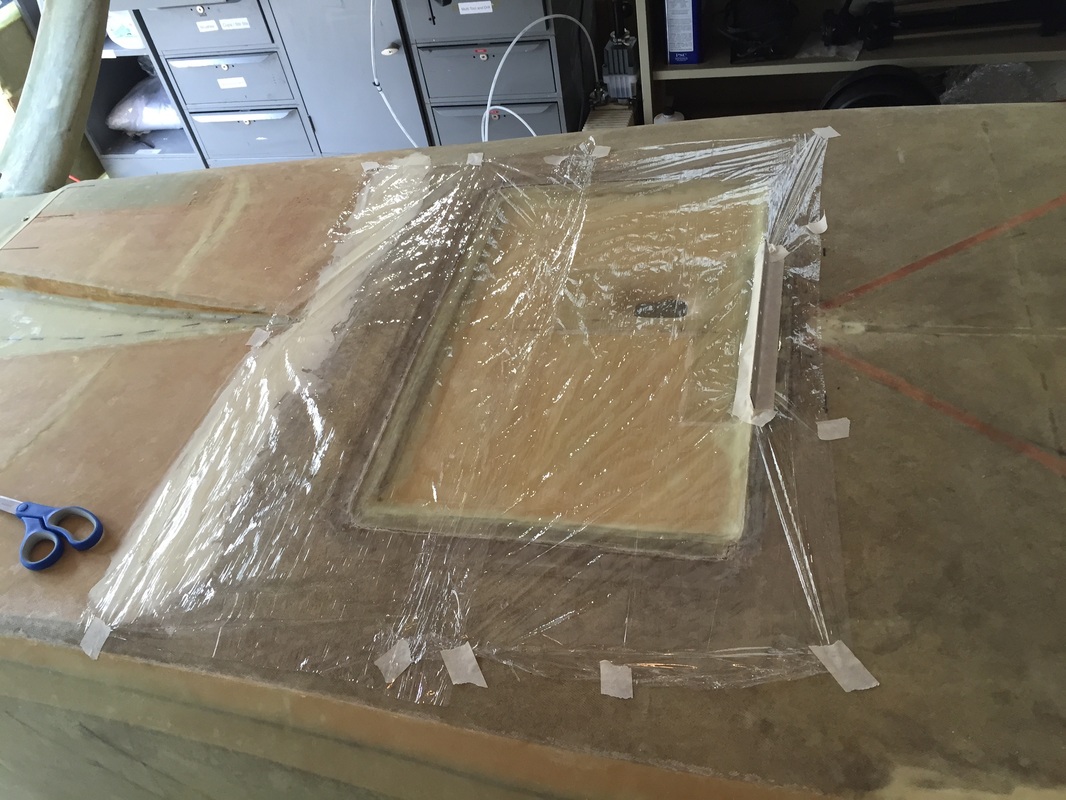
pallet wrap on bottom of fuselage prior to laying the partly cured and brake panel. Don't want anything to stick to the fuselage...
|
I also don't have a picture of David's landing brake, but it was not useable. It had to be replaced. It also provided me an opportunity to work with vacuum technique since it was a fairly flat part, and presented a challenge that helped me grow in solving problems. This challenge was associated with making the new part fit the profile of the existing fuselage bottom without having been cut from the fuselage. The curvature is slight but it was both in longitudinal and transverse directions.
One part of the problem with the existing brake was that the leading edge was not recessed enough due to the hinge not being set deep enough. I removed the hinge and slotted the mount holes slightly to allow for this correct positioning. Shaping the rest of the brake panel allowed it to fit completely flush all around. The buildup followed the plans accept that I had to create the sandwich that was normally formed when the bottom was played up. I did this by making a pattern from the depression (not the previous brake panel) and shaping the foam to this pattern. I then did a benchtop layup of both sides of the brake panel with a new plywood reinforcement panel emplaced in the foam and peel ply/paper towel/pallet wrap on both sides and to form a complete vacuum bag as described by the Cozy Girls. I ran the vacuum for 2.5 hrs before transferring the whole panel system to the bottom of the fuselage (which was turned upside down). I knife trimmed the panel at this point to match the outline of the tapered recession and used flexible wood and weights to force it into the contour of the fuselage bottom. At that point I removed the pump hose and let cure. 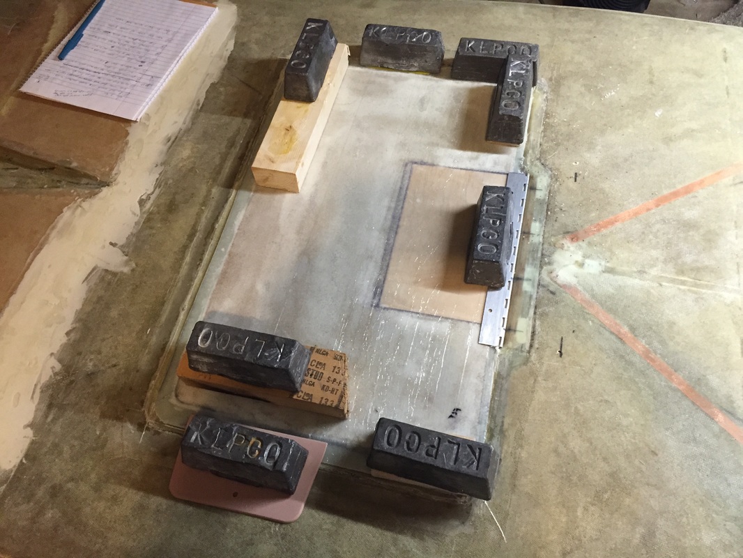
Brake panel system (all of it accept the initial pattern) flipped over and transferred to the fuselage, knife trimmed on the visible edge of the fuselage/brake depression, and weighted down to match fuselage flush everywhere
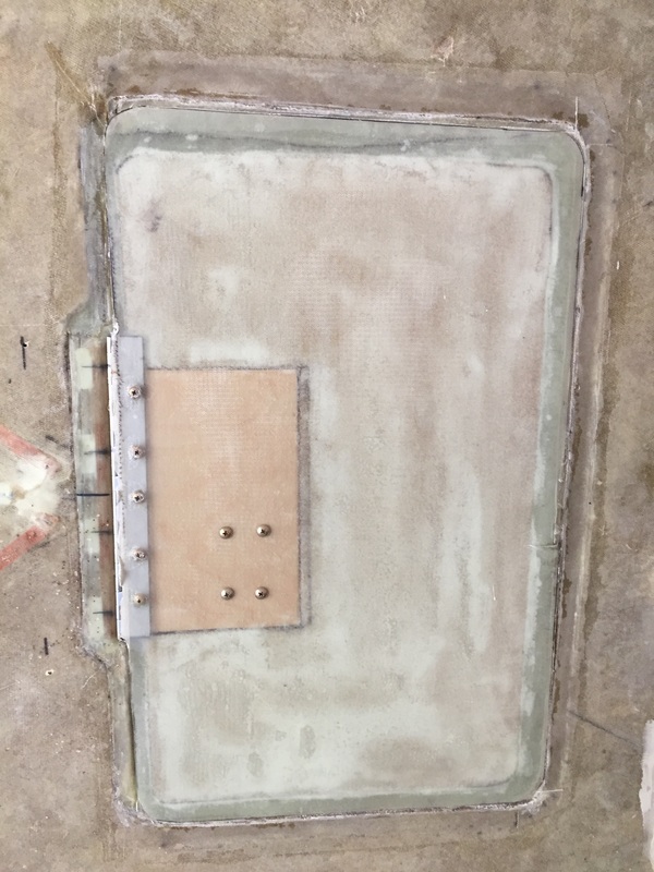
Finished new Landing Brake Installed
|
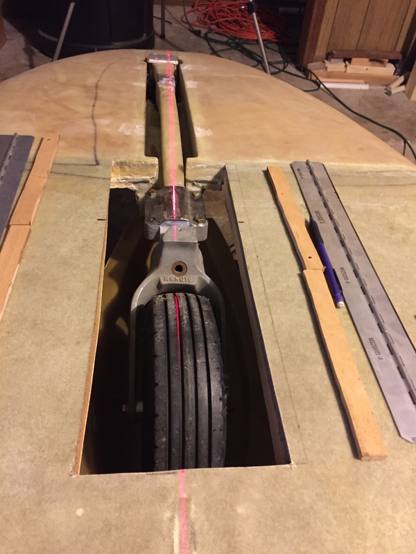
NG 30 Alignment
|
I used a laser to inspect the centerline of the fuselage and it looks great accept forward of F-20. Here I found a slight offset to the pilot's side at F-0 indicating that this forward section had a longitudinal alignment of 1/2 degree. Because it it only on this forward section, I'm going to accept it since the nose is so small, and the work to remove everything does not seem justified unless I find excessive trim needed in early ground and flight testing. It will be painful if I have to come back to this then, but at least by then I'll be experienced.
6 months later: As I look at this again, I still think this is a good decision. The flight characteristics are not likely to be impacted by this, and my expertise is much better now than if I'd tried to tackle it immediately. the fact that the NG 6 pivot point is offset about 5/8" in the longer nose can be more than compensated for with the caster at the base of the landing gear strut. It's something I'll have an eye on as I begin ground testing, and if it's an issue, I'll do what it takes to resolve it then. |
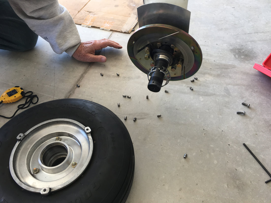
Wheel Bearings Lubrication:
When the wheels come to you they likely have the bearings in them, but maybe they will be in separate packaging. Because I bought a project they were fully assembled in the wheels already. A key thing to remember is that they still need to be lubricated by packing with grease. I didn't dissassemble the main wheels for a year or so and when I did, they were not greased yet. I thought at the time that since I was likely to remove and replace them a few more times (when working on brakes or other) during the build, and the plane was not rolling anywhere significant (driveway and back) I would leave the bearings dry to reduce the messiness of the grease. THIS WAS NOT A GOOD IDEA: In the mass of things I was thinking about when I'd moved to the hangar, I forgot to go back and grease them (the nose wheel bearings were greased well and were fine). The result was that I did a few taxi runs with dry main bearings and destroyed one. A stupid and avoidable mistake. Nothing else was damaged because I was just taxing around, but don't put yourself in this risky position. Grease the bearings when you install them the first time. Here's what they should look like with the grease packed (I did these by hand) and spread some on the wheel bearing race area before contact with each bearing. Keep the work area and your hands clean of dirt/grime before starting this job. It's not hard.
When the wheels come to you they likely have the bearings in them, but maybe they will be in separate packaging. Because I bought a project they were fully assembled in the wheels already. A key thing to remember is that they still need to be lubricated by packing with grease. I didn't dissassemble the main wheels for a year or so and when I did, they were not greased yet. I thought at the time that since I was likely to remove and replace them a few more times (when working on brakes or other) during the build, and the plane was not rolling anywhere significant (driveway and back) I would leave the bearings dry to reduce the messiness of the grease. THIS WAS NOT A GOOD IDEA: In the mass of things I was thinking about when I'd moved to the hangar, I forgot to go back and grease them (the nose wheel bearings were greased well and were fine). The result was that I did a few taxi runs with dry main bearings and destroyed one. A stupid and avoidable mistake. Nothing else was damaged because I was just taxing around, but don't put yourself in this risky position. Grease the bearings when you install them the first time. Here's what they should look like with the grease packed (I did these by hand) and spread some on the wheel bearing race area before contact with each bearing. Keep the work area and your hands clean of dirt/grime before starting this job. It's not hard.
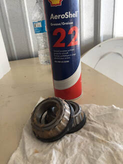
What you Don't Want to See: Inner wheel bearing destroyed by mid to high speed taxi without wheel grease
|
Greased bearings: I even put a little more on them than this and put a layer of grease on the wheel bearing races before pressing them in place. All good now.
|