Chapter 22.1: Electrical/Instrument Panel
Planning out the Instrument Panel
|
I put paper EFIS and radio controls on my instrument Panel (IP) early in the build to help with the dreaming/motivational aspect of building. By the time I finished painting the interior (see finish Chapter 25, which I did out of order) I was ready to start work on getting the panel laid out for real. I kept ideas over the years of work, looking at what others have done, and refined it for the decisions I'd made above. Once I had a rough Powerpoint layout I liked for the big parts and the switches I traced a paper template of the IP and got the ruler out and drew in all the switches and taped on the EFIS and radio candidates then taped it back up and put pillows in the pilot seat to mimic my planned sitting position. After getting used to this a few days, I moved a few things around a little on the paper template, then used it to drill the switch holes and install the switches and warning lights. Here's a view of both the paper template early thoughts on layout of avionics. I'd bought the switches at this point, but still not the EFIS or radios, etc.
|
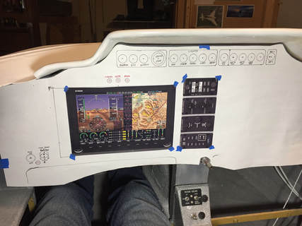
Paper template to judge locations for everything, move them around, and then drill through (1/8") the centers of switch holes. Then paper off and complete the holes for switches...
|
Switches and EFIS Installation
|
I tried to flat black paint the IP, but I just didn't like the way it looked since there was too much underlying fiberglass texture that was not uniform around the periphery. I also wanted to do good lettering. So I followed the lead of Bernie Siu and others by developing a vinyl print from a local printing shop. I used the paper template shown previously to CAD-up a pdf file that I had printed at a sign shop on vinyl and my wife helped me get it applied to the IP without bubbles (it's definitely a 2 person job). Make sure the surface is very smooth and clean to enable the vinyl adhesive to gain a strong grip. I had already cut all the switch mounting holes with a drill, which meant that I needed to use a razor blade to cut the little vinyl circles out in front of each hole (as well as the holes for the air vents). This wasn't hard because you could feel and see the hole edges with a little angled light. Cutting the IP for the EFIS and radio (below) was done by first mark/trim the vinyl with razor blade, remove the vinyl rectangle, then cut the IP with dremel wheel and corner grinder.
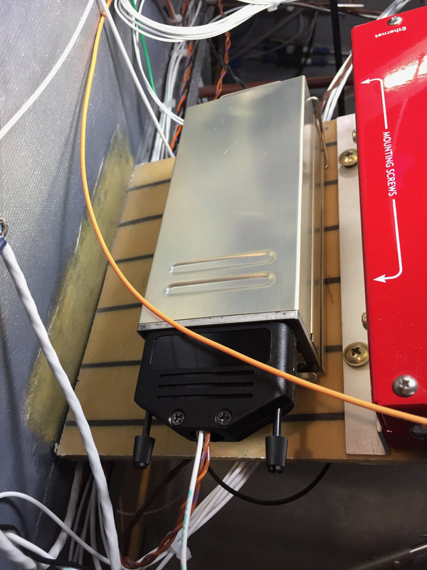
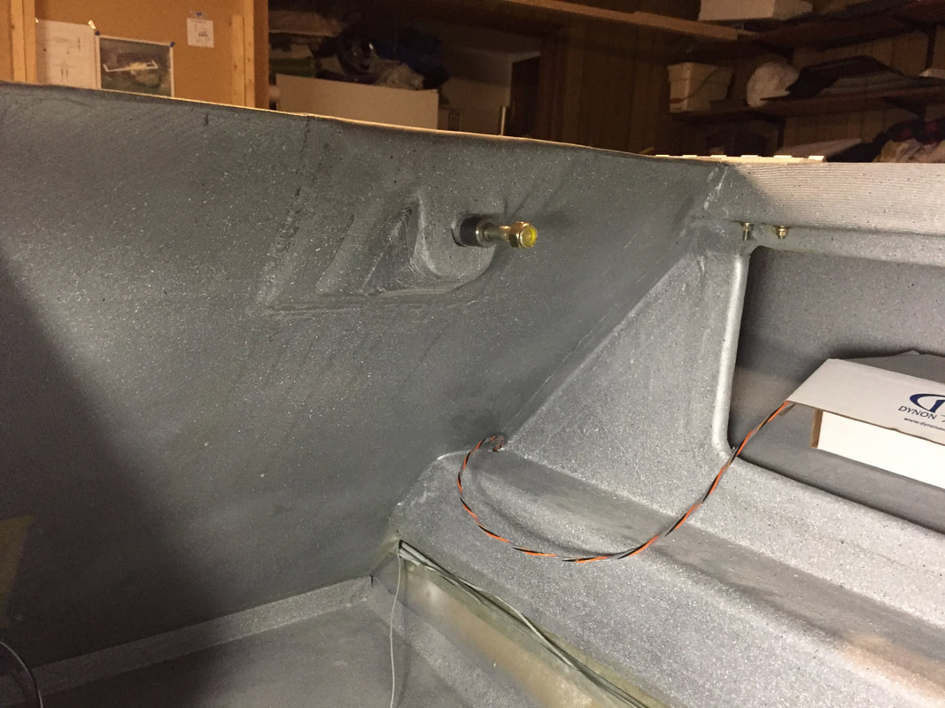
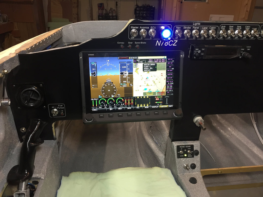
It was at this stage that I made the purchases for the EFIS and radio/intercom. I'd pretty much decided to use Dynon Skyview (SV) and splurged on the HDX1100 and followed Neal Johnson in using the Garmin GTR200 radio/intercom. It's a not an inexpensive approach, but is pretty well integrated and I liked the layout of the Garmin over the SV radio option. Both however are good. You will see I use "EFIS" and "HDX" interchangeably from here on through the website. After a week of working on wiring and occasionally sitting on pillows getting a feel for the cockpit, I realized that the EFIS view angle is not ideal (my opinion) when mounted flush in the IP. This is in part because I want my eyes relatively high locking over the panel and down the sides and the screen is facing my lower chest. I noticed someone a couple of months prior on the builders email list talking about tilting the IP top forward a little to improve this view angle for modern screen based avionics. Since I'm not going to tilt my IP at this point, I decided to look into tilting just the EFIS. The result with a couple of 6061 Al 1/16" thick sheets is shown to the right. At this point the screen is facing my neck, which feels much more comfortable a viewing angle. It's firmly mounted to the panel and I painted the Al plates black to make them harder to see (pictures to right)... Word of Caution: Tilting the bottom of the EFIS out like this does reduce it's clearance with your shins when you bring your heals up close to the IP. I tested it, and it was fine for me, but probably will require more care to manage in and out with a taller pilot. I've considered making this a movable tilt, so that I can push it flush with the IP whenever I want, but that will be a mod for after Phase I flight testing. |
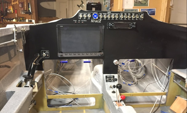
IP with vinyl covering, switches in, and HDX1100 + GTR200
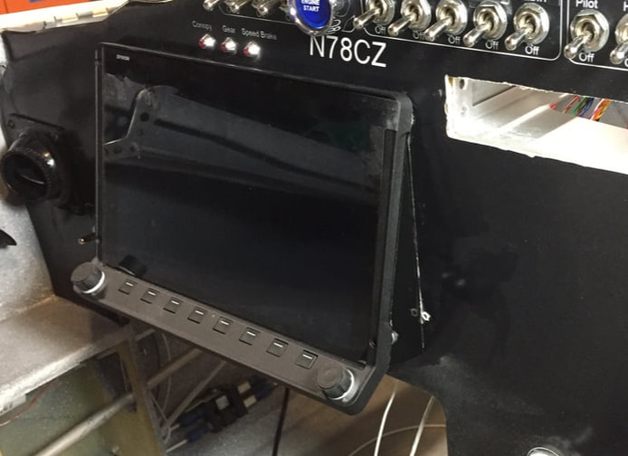
I tilted the HDX up with aluminum side brackets to aim the screen so I can see my neck rather than my belt in the reflective film (which comes off). I need to measure this angle still...
A view of the tilt brackets from the back side...
|
Powering Up the HDX1100 and Integrating the Skyview System
|
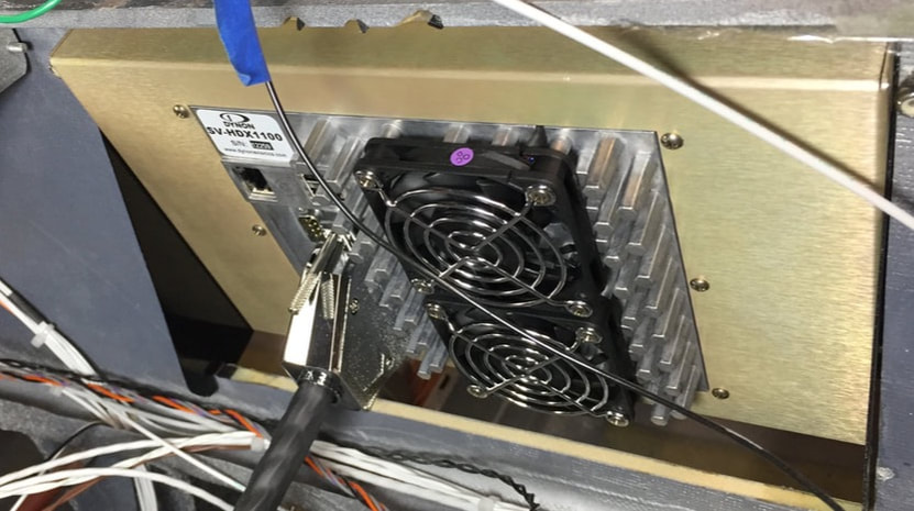
Before doing anything with the EFIS/HDX I worked on getting all the switches and other circuits checked from the VPX (see Ch 22 page). Then I connected the HDX to the VPX and it powered up perfectly when the Master Switch was closed (note the SV-HDX EFIS is designed to be connected this way and has it's own battery backup, that I also had wired up before booting the EFIS the first time. The HDX1100 has these other components connected to it as outlined below: SV Transponder: This unit is powered by the VPX when I close Avionics switch on the panel. Pilot control is through the EFIS and the actual transponder box is located on the same shelf as the VPX. I built the connector for power from VPX, ground, and data exchange with the EFIS as well as buying a BNC/BNJ equipped RG400 cable of 35" length and used the Archer dipole antenna mounted as far forward as possible in the nose co-pilot side wall. This remote transponder module is mounted on the same shelf as the VPX, fwd of the copilot side IP. SV ADAHRS: My ADAHRS is mounted under the pilot's thigh support, where it's easy to run the pitot/static, OAT, and Skyview net cables and it's very close to the CG of the airplane as recommended. This location is also at least a couple of ft away from the nearest actuator (pitch trim) and 4' ft away from the nose gear actuator. After completing the plumbing of the pitot and static lines to the ADAHRS, I connected the OAT sensor and mounted it inside the pilot side NACA vent. The sky view Net cable was made from a SV-NET 10 ft one ended cable by cutting to length (~ 5ft) and crimping all the right pins in the 9pin D-Sub connector. SV Engine Monitoring System (EMS): I considered a lot of different places to put this little box and ended up choosing a place I hadn't seen anyone use. I built 3 BID mounting flanges on the forward face of the main spar on the pilot side and mounted it there to keep it off the firewall (where I wanted to mount the bigger Engine Control Unit from UL. Both will need to be pretty close to each other and the firewall so the Skyview Network cable would need to be 10 ft to reach here. I bought the one-ended network cables from Dynon and made the connectors to go in the EFIS. The 10 ft version was just the right length when running in the pilot side electrical conduit path. SV GPS 2020: I also looked at a lot of options for placing the GPS. I chose to put it in the canopy high behind the turtleback bulkhead so it had maximum view of the sky and was away from the transponder and radio. The wires run under the Co-Pilot armrest from the HDX and the GPS mounts in a 3D printed plastic bracket I made, which screws to the turtleback bulkhead. I wired a connector at the canopy hinge line behind the copilot seatback for canopy removal. I'll get pictures of these here soon. I followed he SV Installation manual and so far, the HDX discovered everything on the SV Network and the GPS and the VPX (inserted the required license code). The only components I've not checked are the radio and transponder (they get power separately via the Avionics switch). Note that the whole SV system is powered up when the master switch is closed and the system is backed up from the separate SV battery. Note also that you can power down the HDX system and these other components even with the master switch closed, if you need power for something else while on the ground. 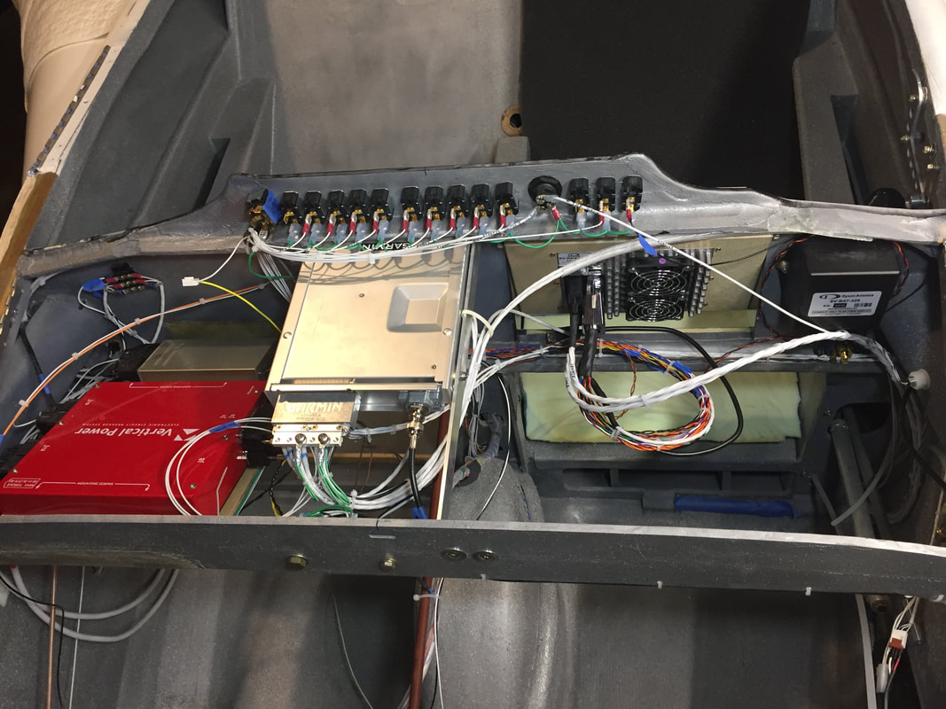
A look at the back side of the IP after wiring most everything up... Looks pretty similar to Neal Johnson's configuration
|
SV 261 Transponder located just in front of Co Pilot Instrument panel on a wooden shelf with VPX.
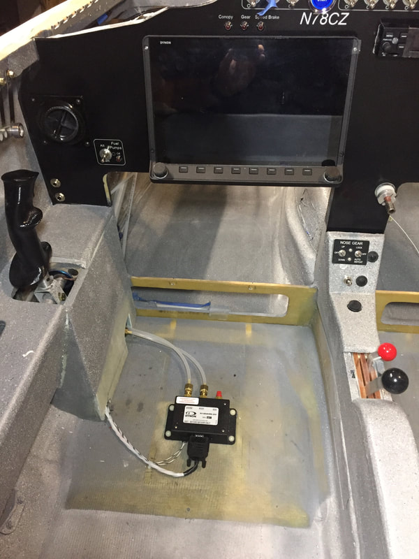
SV ADAHRS mounted on floor under Pilot thigh support
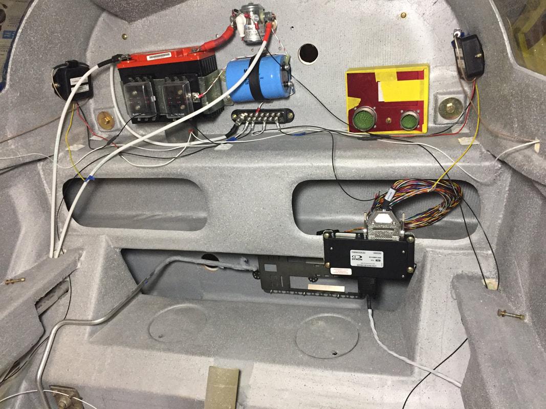
SV Engined Management System (black box) mounted on lower front face of the main spar. The UL Power Engine Control unit with yellow tape is a mock-up box they sent me while waiting for the engine so I could work out where I wanted to put it. You can barely see the dual fuel pump bracket (empty still) down in the hell hole on the inside for the firewall.
SV GPS 2020 will be mounted in the canopy just behind the top of the bulkhead, but for now, it sits in it's box (but connected) in the right rear cargo area)
Yea! HDX is working! Much more setup to do, but so far, so good.
|
Wiring up the GTR200
|
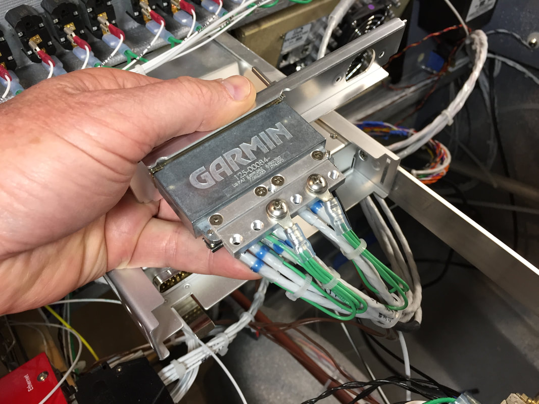
Getting this component all wired up (including positioning and wiring the headset/mic jacks and stereo jack and connecting to the HDX audio) took me about 8 hours. There are 6 shielded cables coming in to the back and I was being extra careful to keep the area clean working around these RF lines with shield stripping and soldering. All of the shields were grounded to the Garmin connector block and not on the other ends. I used solder sleeves for the first time and they are convenient for attaching the green ground wires. The Stein Youtube videos were very helpful for handling all this stuff. I followed the SV install guidance and coupled it's stereo output (L&R) and fed them to the AUX 1 input of the GTR200 so I could use the stereo input on the GTR for a stereo jack on the Co-Pilot side of the IP. Mostly, I just did this very slowly, double and triple checking all the wire colors before they got covered up at both ends, and making sure I had the wires running in a reasonable way to allow the connector to be pulled out of the way if needed (even though the GTR slides into a rack with a semi-permanent connector rear panel, you can see in the picture).
|
|