Ch 25.4 Finishing Fuselage/Strake/Canopy Top Side
|
General Note: all my glass work is MGS 335 with slow hardener and the filler is West 105 with slow hardener and West 410 filler. I know the 410 is expensive compared to micro, but I got it much cheaper on Amazon in bulk and compared to the cost of most other stuff I'm doing on this airplane, I believe it's worth it for this job. It feathers very well, and once I got used to mixing it thick enough it's really fast and easy to spread and sand and is supposedly slightly lighter than micro. (I've not verified this)
Strake Fairings:
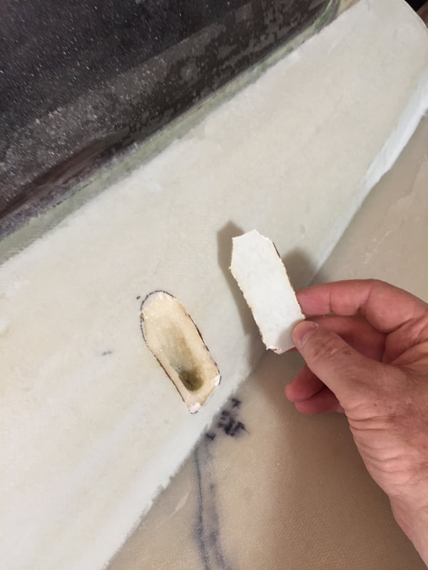
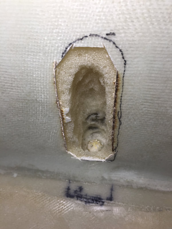
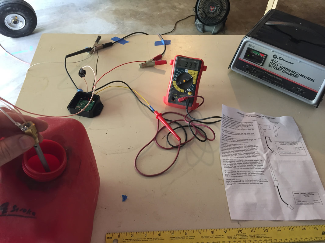
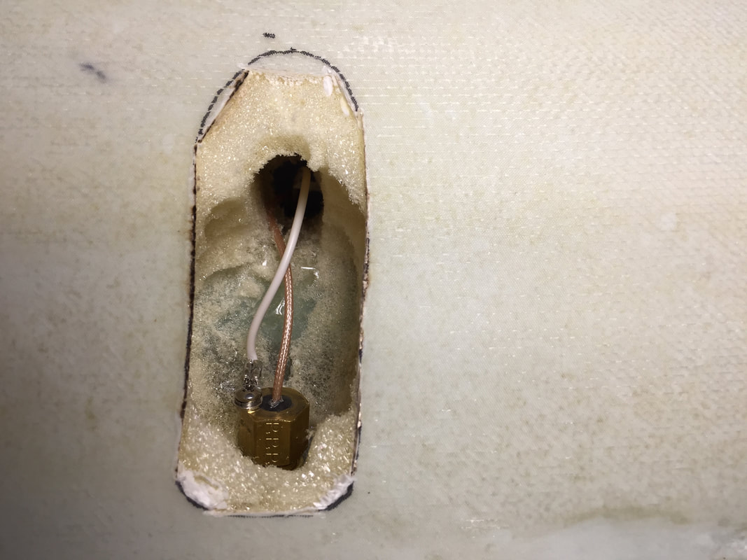
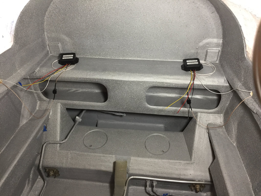
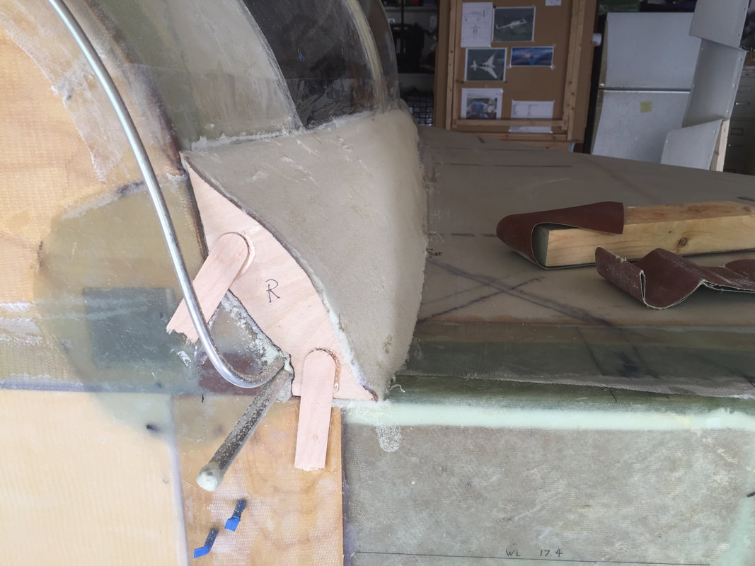
After flipping the fuselage back upright, I built the strake top fairings. I used the pattern from the plans for the firewall profile of the fairings so the standard cowlings should fit, and built them up using pour foam. To do this, I used a "dam" made from scrap piece of 1/4" flexible plywood and covered it with pallet wrap to keep the foam from sticking. If you've read much of my site, you know this stuff is pretty tricky to work with in terms of timing: stir the 2 parts, and as soon as it starts to grow, pour it in. If you wait too long, it gets sticky and won't pour well. It took 3 small batches of pour to do each side. Looks ugly, then you go to work on it (see pictures) and it comes out great. I find the pour foam to be quite easy to shape and it's nice and stiff compared to the urethane prescribed in the plans. See pictures to the right -> I then created the access and installed the capacitive fuel probes that are buried in the fairings by cutting out a small panel, carving out the foam, drilling the TB to run the wires inside, testing the probes to make sure they work, and replacing the dummy plugs with the actual probes. See picture sequence below:
|
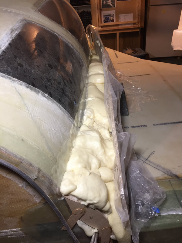
Pour foam fill between TB and plywood "dam" covered with plastic for easy removal
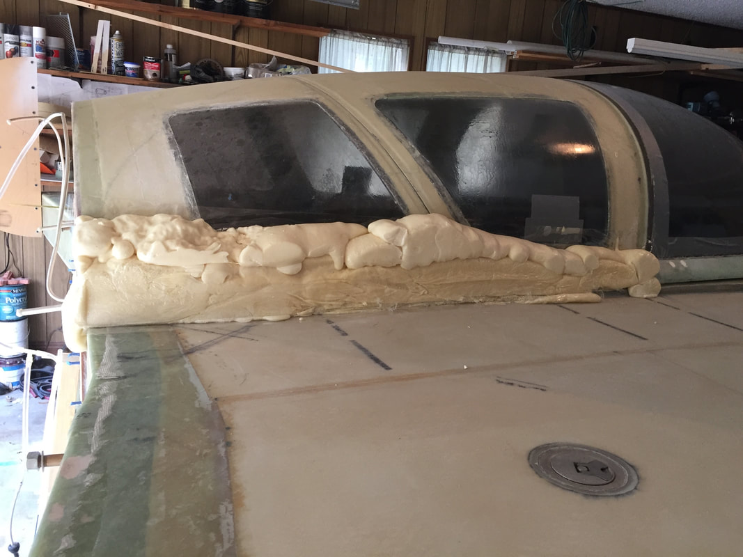
Ugly pour foam after removing the plywood dam
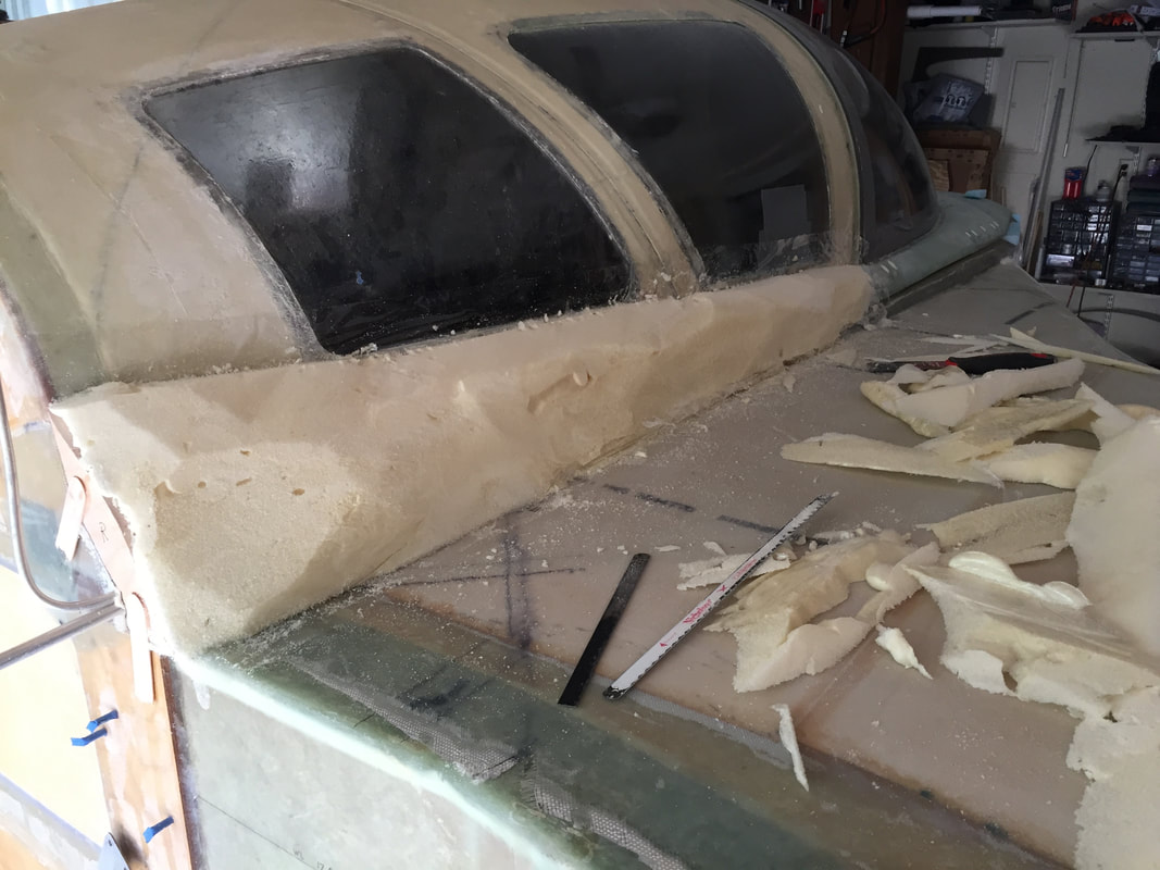
First trim with hacksaw blades...
2nd phase shaping with cheese grater (Stanley is what I have)
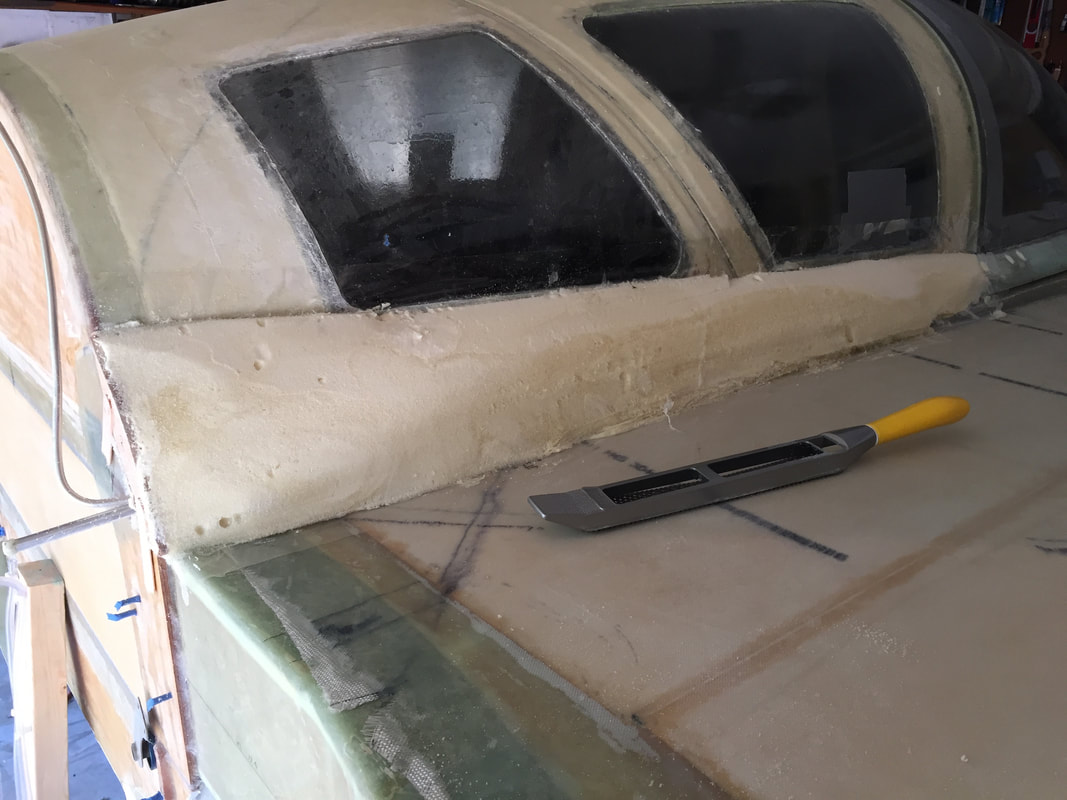
3rd Phase shaping is 80 grit sand paper. Many passes, with rest between.
Hard shelled, then 2 ply UNI (it's what I had more of, and it's cosmetic only) and peel ply
After canopy cut-out. This is the more interesting pilot side...
|
|
Strake Tops:
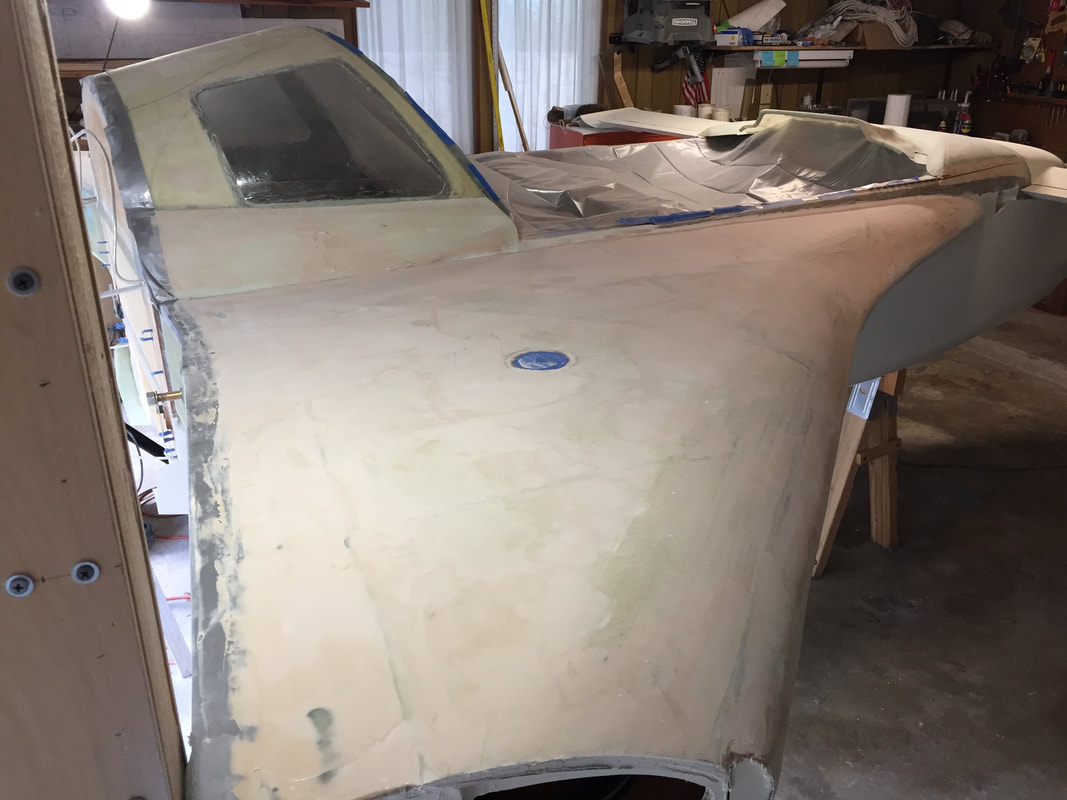
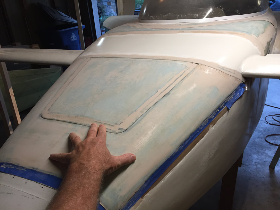
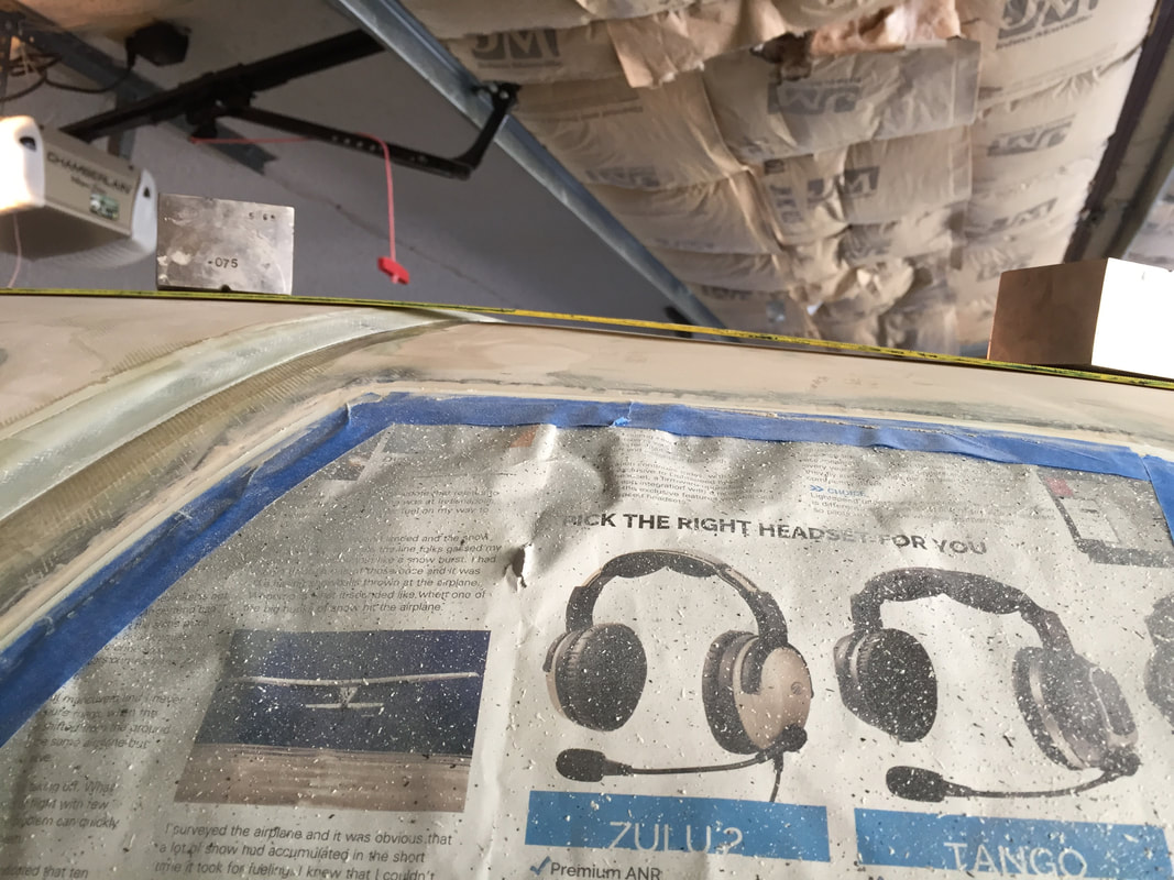
Used the same method of fill and sanding as on the bottom skin of strakes, so not putting a lot of text in here. There's more shape on the top skins, particularly near the leading edges and they have the gas caps, but that's the only difference for finishing. I masked the fuel filler cap and the aft 2 inches of the spar for later building the glass flange for cowling and eventual smoothing into the wing root elements. The picture to the right also shows the plastic I used over the cockpit when I had the canopy stored in the house. Lots of dust being generated and it covers EVERYTHING. I vacuum the floor and the plane often to keep it down, but shelves and benches will have to wait until I complete the finishing stage later this year... |
|
|
Nose Top/Canard Cover/IP Cover/Canopy LE:
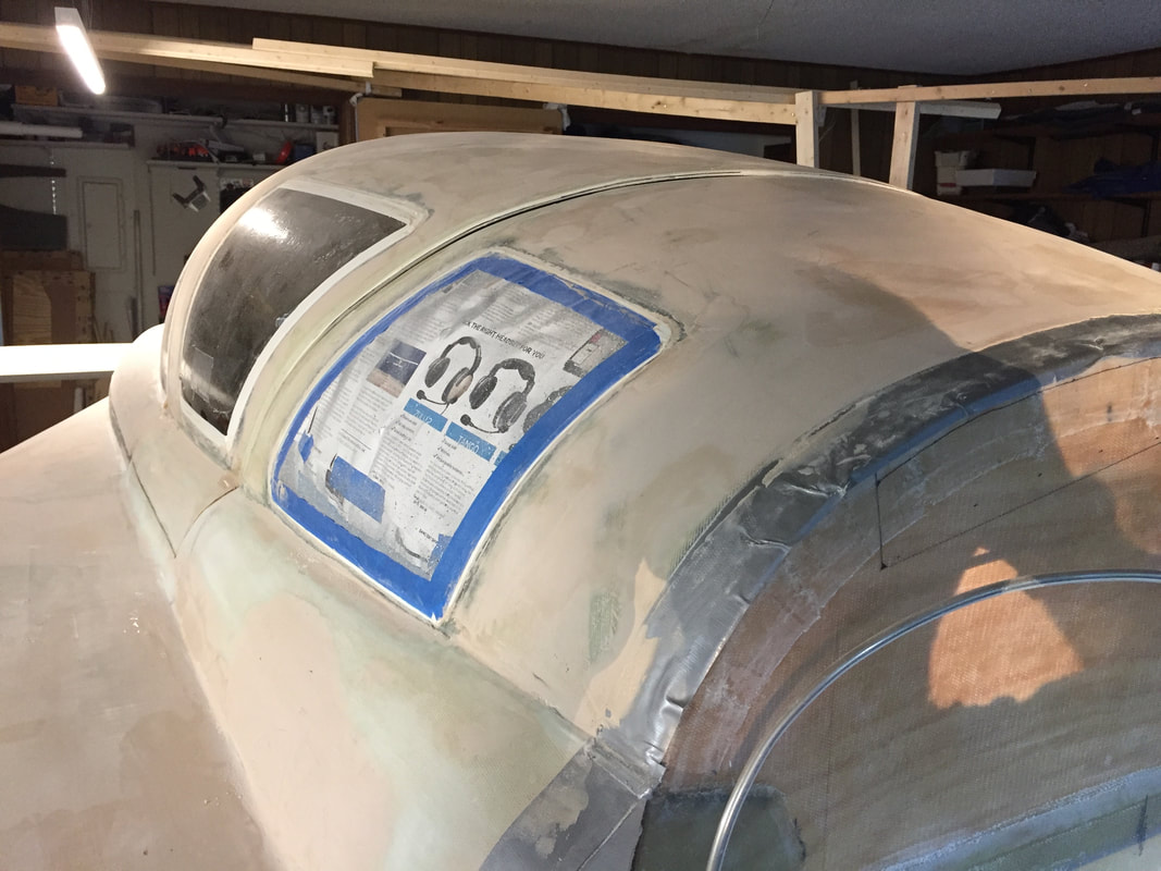
This section of work really was an iterative process in patience. There are many components with interfaces on the upper half of the fuselage, and they all need carefully smoothed seams with each other. I'd done a little bit of seam work on the underside around the landing brake and the landing gear cover, but this area is the most visible. Tips: - have strong lip layups (I used 2 or 3 BID when overlapping to the rear, and 3 BID when overlapping forward into joggles). Filler is not strong, and needs to adhere to lips. - I used packing tape under the lips to make sure that any filler would not bond the separable parts at the lip interface. - In the 1st fill, I also used some pallet wrap that could come through the lip interface and stick up even in curved regions, to help me see where the interface line is, under potentially 1/16" thick filler. I think used a box cutting knife to cut this line about 1.5 hrs after the spreading when the West epoxy had reached a rubbery state. At this point it was easy to cut, but would not flow back and bond. When fully cured, light sanding would clean up the seam. - remember that you may have to do this several times, sanding between each one to get the seam even and flush, and catch the occasional pin-holes. - Exotherm: it's important to get the West epoxy out of the mixing cup and spread out at least a little within 10 minutes of mixing with filler when the temps are above 83 degree's (typical in my garage in July) to prevent exotherm heating. Once it's spread even a little, the self heating is reduced significantly and you have more time to work with it. If you let it get too far along in the cup, the filler firms up and makes tiny bubbles within and it's useless. I had this happen a couple of times when I mixed more than about 30-40 grams of resin (my metric) and had lots of small filler spots rather than one larger area to work with, which delayed me getting it out of the cup... OK, pictures...
|
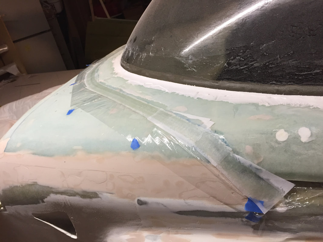
Early look in the process:
1. gap between the IP cover and the longerons (my IP cover is one piece all the way to the back of the canard cover)
2. Gap between the canopy frame on pilot side to longeron will get glass flange later
3. I've removed tape around lower seam of canopy window to frame and will re-tape with electrical tape after re-applying the disc-coat window protection layer (easier to remove and no residue so far. This re-application of tape is to more carefully shape and control the micro-fillet and paint line on the canopy window later.
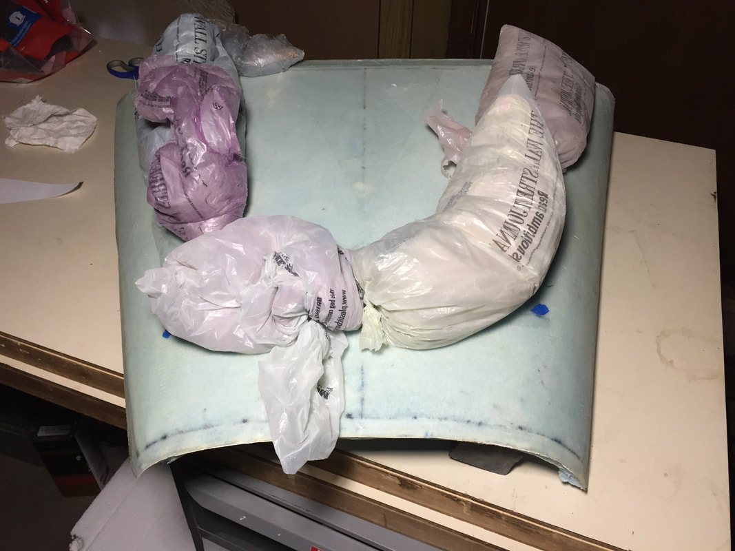
Plastic sand bags (newspaper delivery bags) to hold the nose top hatch in place, and the 3 BID lip flush into the joggles.
Early fill/sand iteration in the nose to canopy area. Note that my nose top is not yet glassed on (blue masking tape preserves raw glass surfaces for after electrical work is completed, when I'll attach, fill, smooth and prime this area.
|
Canopy Mismatch to TB:
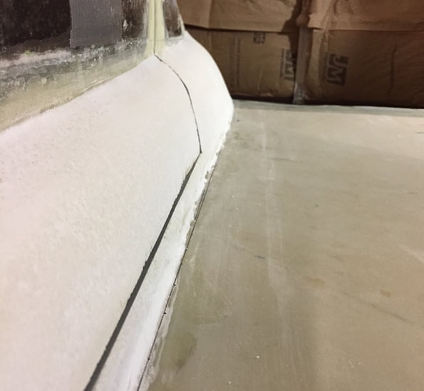
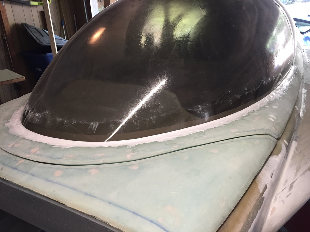
Others have noted how the aft edge of the canopy (at the cut line between the TB windows) can become mismatched later after heat/cooling cycles and storage. I thought I'd mitigated this by putting a small support rib back there (see Ch 18, Part III) but after more than a year of storing the canopy level and covered in the house I still had a little mismatch in this area as shown. It's a good thing I'd not yet built the lip for this seam, as I would have probably cut it off and built it again, AND that thin edge would have been more vulnerable to damage in storage/moving. The maximum mismatch was about 1/4" so I decided to just fair it into the stationary portion of the aft TB. So far, it looks fine, it was just more work and a little more fill weight.
Others have noted how the aft edge of the canopy (at the cut line between the TB windows) can become mismatched later after heat/cooling cycles and storage. I thought I'd mitigated this by putting a small support rib back there (see Ch 18, Part III) but after more than a year of storing the canopy level and covered in the house I still had a little mismatch in this area as shown. It's a good thing I'd not yet built the lip for this seam, as I would have probably cut it off and built it again, AND that thin edge would have been more vulnerable to damage in storage/moving. The maximum mismatch was about 1/4" so I decided to just fair it into the stationary portion of the aft TB. So far, it looks fine, it was just more work and a little more fill weight.
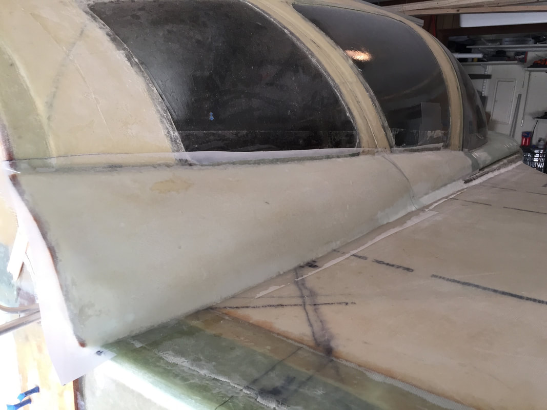
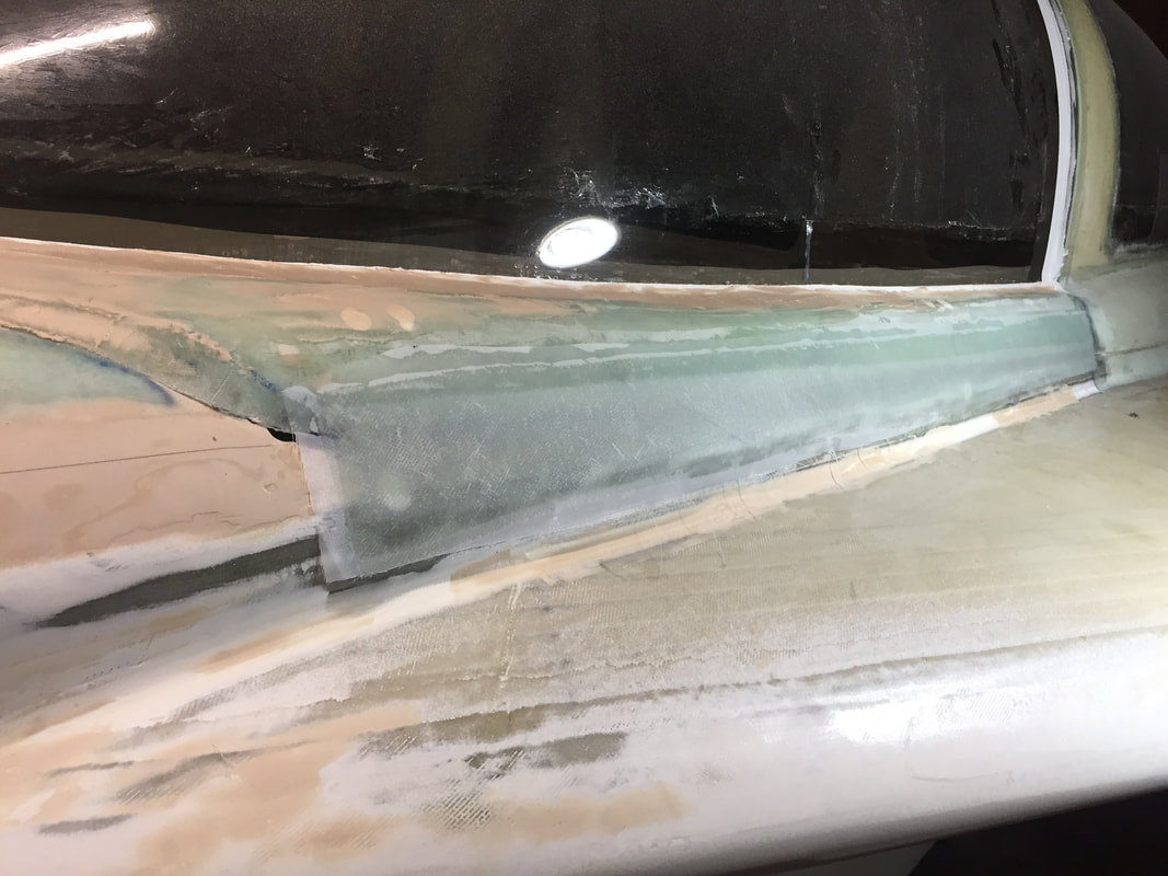
canopy latched and you can see the mismatch in the top part of the Canopy on this aft seam. Sides match fine...
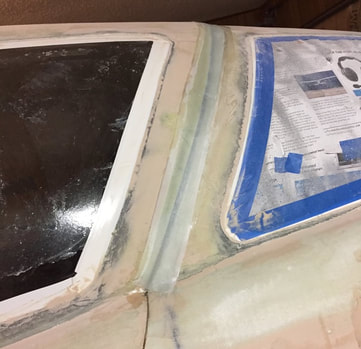
I glassed the lip so that it bridges the gap with 3 BID per plans (shown) then built up a 50/50 flox/micro layer on top of this glass that was then sanded flush when sanding the aft fairing on the TB. This gave the lip more strength in this area.
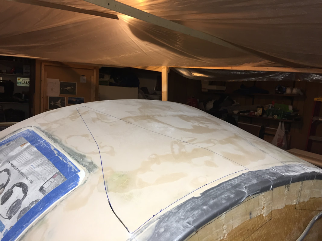
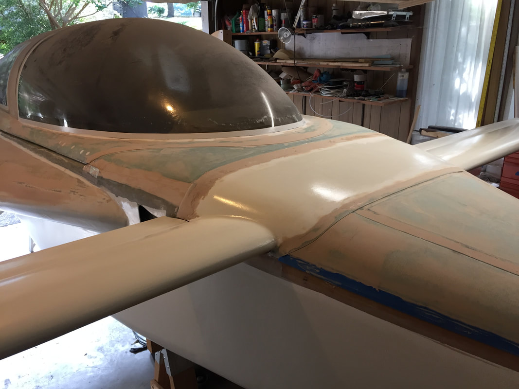
Here's a look after several cycles of fill and smooth and you can also see where I'm marking the surface to cut out the NACA scoops for downdraft engine cooling. More on this in the next section.
|
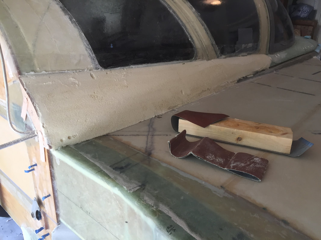
I used a steel ruler and 2 weights to gage what the fairing profile should look like in the worst section.
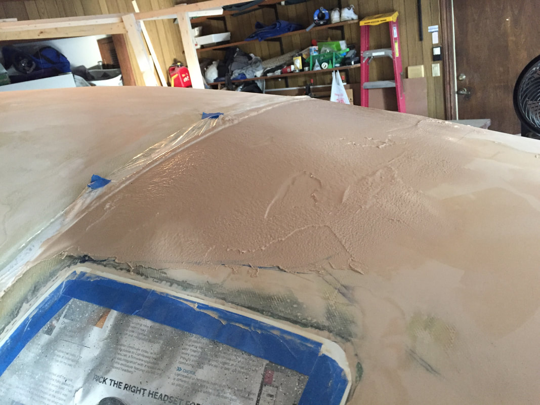
Here's the first application of West 410 filler on the aft TB area before smoothing. It will take 4 cycles of fill/sand to get this area to acceptable fairing for me.
|
Engine Downdraft Cooling Scoops:
As I get to this stage in the build I'm having to come to grips with my engine selection, and preserving the option of UL Power 520is OR the Lycoming 360 options. I'll cover this more in the Ch 23 Engine section, but what's important here is that I've decided to take the leap in preparing for downdraft cylinder cooling required for the UL engine. I'm closely following the work done already by Ryley Karl and Greg Cross, both of whom have bought their UL 520is engines and made the modifications I'm covering here. With Ryley's permission, I've included a photo of his installation so you have a feel for what I'm going for, once the engine is on. He's done beautiful work.
As I get to this stage in the build I'm having to come to grips with my engine selection, and preserving the option of UL Power 520is OR the Lycoming 360 options. I'll cover this more in the Ch 23 Engine section, but what's important here is that I've decided to take the leap in preparing for downdraft cylinder cooling required for the UL engine. I'm closely following the work done already by Ryley Karl and Greg Cross, both of whom have bought their UL 520is engines and made the modifications I'm covering here. With Ryley's permission, I've included a photo of his installation so you have a feel for what I'm going for, once the engine is on. He's done beautiful work.
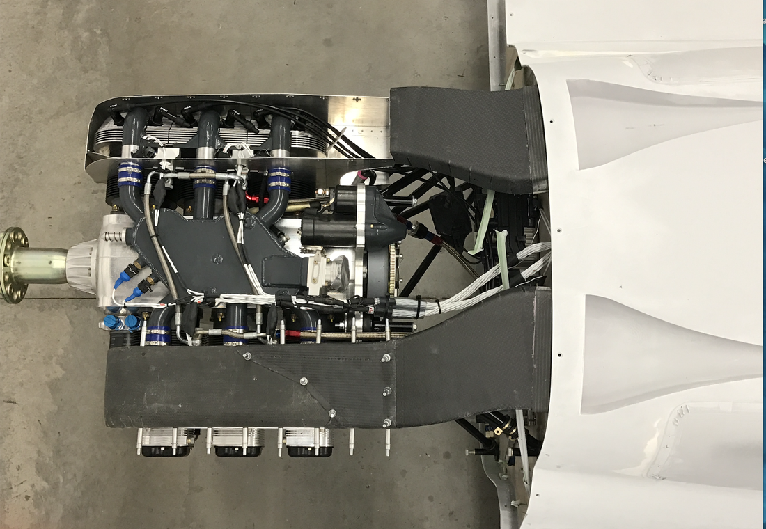
This is a view of Ryley Karl's downdraft system on a MKIV with the UL Power 520is. It's based on the approach taken successfully in Velocity canard aircraft. I'm following him (Greg Cross is using same method) with the NACA scoops in the aft portion of my TB.
|
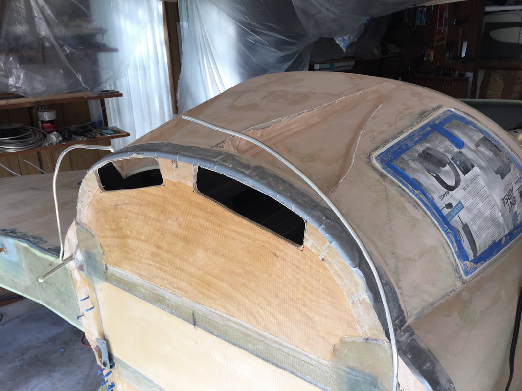
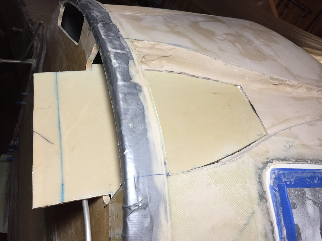
An early view of my NACA scoops being formed in the aft TB and the associated duct holes in firewall.
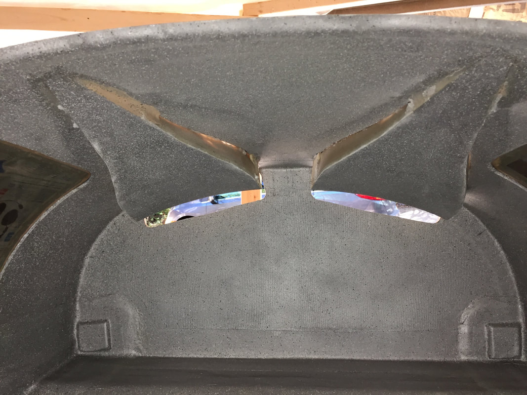
An interior view of same NACA ducts in the early stages of construction.
|
After this initial effort, I wasn't happy with the curvature in the floor of the NACA as it gets close to the firewall. I want it to transition to a rectangular duct as it goes through the firewall and the 2" between this first version and the firewall (see interior view above) is not enough space to make this smoothly. SO... more work. Here's what I did:
Another thing you can see by the end of the pictures below was that I made the foam supports, bonded them temporarily to the aft side of the firewall, and laid up the cowling flange as described in the plans Ch23 page 3, since this needed to be done before the transition duct pieces were in place.
- Cut out the curved floor of the NACA's (leaving the sides that I'd glassed previously) from a point approximately 9" forward of the firewall and 7" forward of the NACA aft lip. Remember that this original floor piece was the old curved skin of the original TB.
- Cut a replacement flat floor piece of 0.2" thick clark foam that's stiffer than the .25" 4.5lb Last-a-Foam used in the TB skin. I used this because its stiffness made it easier to work with for this relatively flat application. The new piece matched the profile of the cut floor piece (when viewed from above) but was long enough to extend 3" through the firewall. When I glassed (2 UNI at 90 degrees to each other, like the original TB outer layup) the top of this foam I matched the lateral curvature of the old floor using a couple of pennies under the mid section and weighting the front corners down. The glass then preserved this curvature match once cured.
- Flox the new floor piece in place of the old floor piece, then glass (2 BID) the underside, lapping up on the sides of the NACA (this is inside the TB)
- Small glass tape (1BID) on the outside seam of the new floor piece to the sides, then micro the NACA fillet in this seam with ~10% addition of flox fiber so it's stiffer than standard micro, but still sand-able.
- Made Clark Foam side pieces and flox/glassed them in to fill the gap to the firewall
- Designed and printed a 3D form to layup 3 BID the curved sides and top of the transition duct extending 2.5 inches aft from the firewall opening and making a 2"x9" rectangular duct interface with 0.5" radius corners.
- Glassed (2 BID) these transition pieces to the firewall
- Apply micro and smooth everything in preparation for primer...
Another thing you can see by the end of the pictures below was that I made the foam supports, bonded them temporarily to the aft side of the firewall, and laid up the cowling flange as described in the plans Ch23 page 3, since this needed to be done before the transition duct pieces were in place.
New flatter floor with extension through the firewall floxed in place. separate note: Silver duct tape you see protected glass of the 2" firewall joggle while micro smoothing the outside skin of TB. This duct tape got removed for the 3 BID cowling flange you see in the picture to the far right.
|
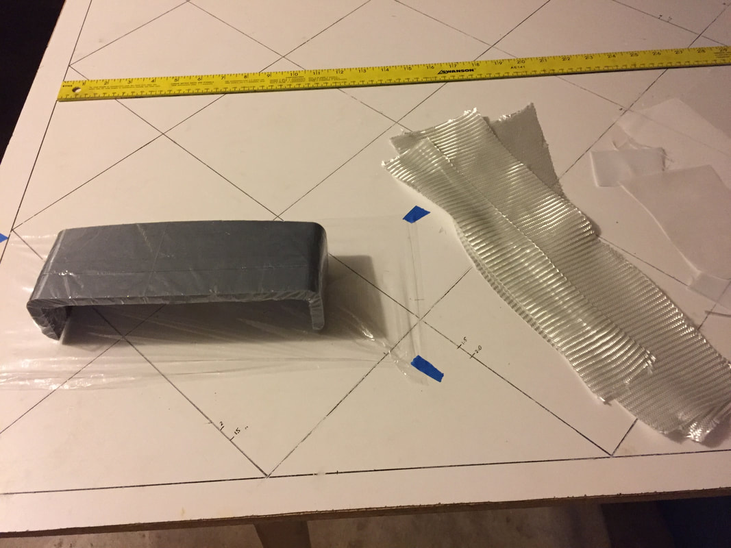
3D printed form and glass and peel ply before making the transition duct pieces that go aft of the firewall
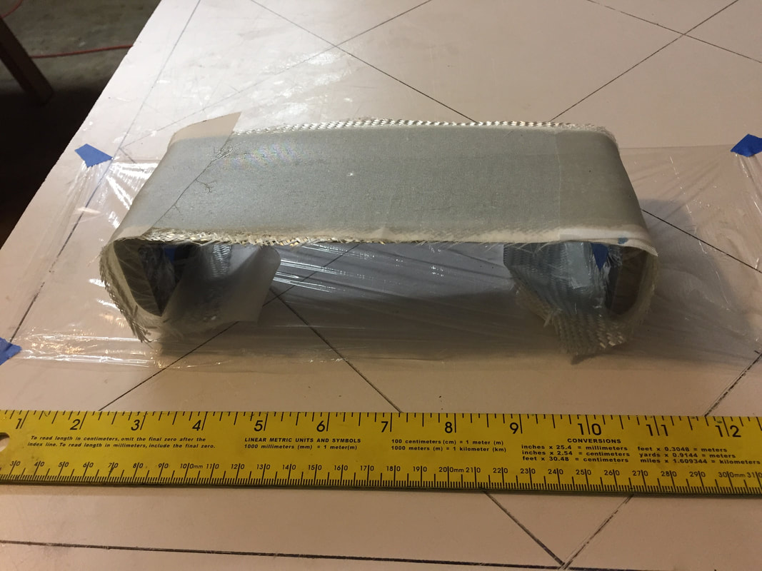
The 3 BID transition duct layup on the 3D printed form. Same form for making both of the ducts.
|
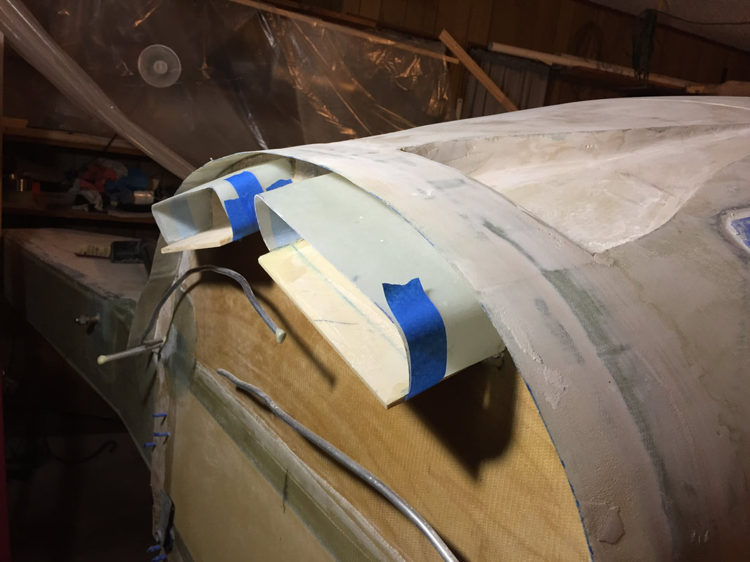
The transition ducts getting 5 min epoxy spot bonded prior to full flox/2 BID taping them to the firewall and the flat floor piece.
|
Preparation and Priming:
Once I had the seams and surfaces faired, I formalized the masking process, re-built the painting booth in the garage and got ready to prime. I naturally continued to find little places that needed some filling and sanding or just sanding, and this just continues until I feel good enough to actually prime the surface. Too many iterations to count. Finally, I resolve to apply the first coat of primer, which will of course highlight all the little imperfections I have trouble seeing or feeling in the imperfect lighting of my garage. First Coat:
Once I had the seams and surfaces faired, I formalized the masking process, re-built the painting booth in the garage and got ready to prime. I naturally continued to find little places that needed some filling and sanding or just sanding, and this just continues until I feel good enough to actually prime the surface. Too many iterations to count. Finally, I resolve to apply the first coat of primer, which will of course highlight all the little imperfections I have trouble seeing or feeling in the imperfect lighting of my garage. First Coat:
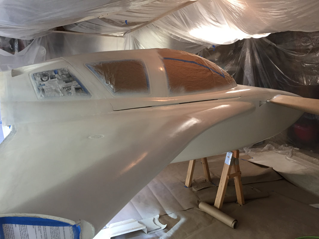
First coat applied: Not perfect and will require some sanding of a couple of orange peal and drip spots. I definitely have some improving to do with regards to optimizing the spray gun setup, but it's fine. Mostly, it shows me where I need to keep working to eliminate small surface fill imperfections...
|
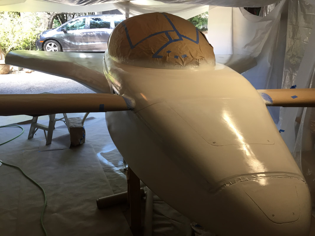
Worth noting here: I'm not yet permanently attaching the nose top piece yet. I've masked around it's sides and leading edges (at F-0) so that later I can glass, final fill, and prime. I'm doing this because I want full access to the nose area until I'm really ready for final finishing. I'm priming a little earlier than the plans suggest to protect the exterior from sunlight as I move on to electrical/engine installation.
|
More to come... 8/20/18. But first, the solar eclipse!
Worked on filling a few spots highlighted by the primer and put a 2nd coat on. I didn't have the gun set up well, so I stopped after doing about 1/4 of the work, and let it cure and sanded it off. Another check and imperfections addressed and re-mixed a very fresh batch of primer and it went much better. 2 Coats is enough for now, since I'm just trying to protect the glass/epoxy and move on to other things (winglet/rudders). I've taken the paint both down and stored components for later, to make room for this wing work and will get a picture here soon when I can push the fuselage out into the driveway.
Worked on filling a few spots highlighted by the primer and put a 2nd coat on. I didn't have the gun set up well, so I stopped after doing about 1/4 of the work, and let it cure and sanded it off. Another check and imperfections addressed and re-mixed a very fresh batch of primer and it went much better. 2 Coats is enough for now, since I'm just trying to protect the glass/epoxy and move on to other things (winglet/rudders). I've taken the paint both down and stored components for later, to make room for this wing work and will get a picture here soon when I can push the fuselage out into the driveway.