Ch 18.2 Canopy
|
Canopy Supplier: I ordered my canopy with 2 other Cozy builders in Central Texas and we saved on shipping having them come together to one place. We ordered from Todd's Canopies, which is no longer operational, but other builders are now (3 years after I finished this chapter) sourcing from https://www.airplaneplastics.com.
|
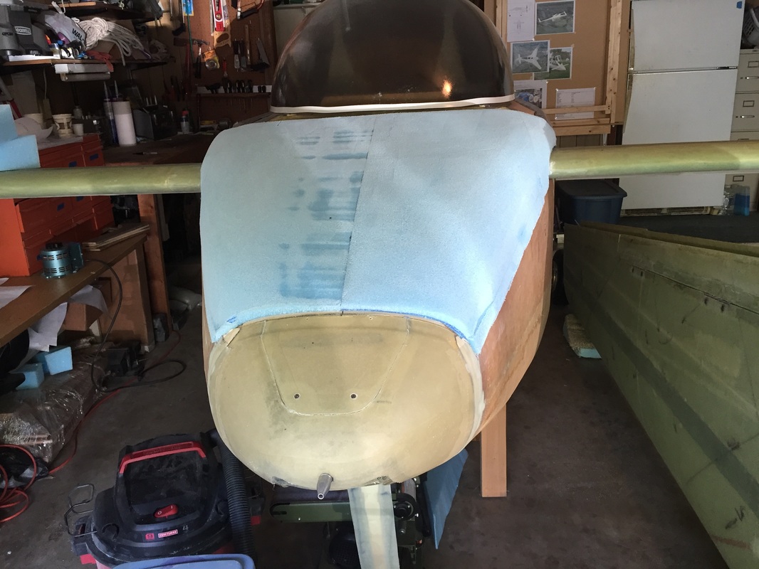
Installing the CanopyReminder: My TB is 38.5 inches wide at the Canopy and it's flange is 1" higher than the longerons at the Canopy interface. It is normal width and height at the firewall so my firewall is built to plans. This means I needed to make tapered foam to fill the space between the TB flange and the longerons, as described in Ch 18 Part I Turtleback page. Before working with the Canopy I insured it had several coats of spraylat on both the inside and outside to reduce the likelihood of damage during handling. I was still pretty careful, because spraylat is not a lot of protection.
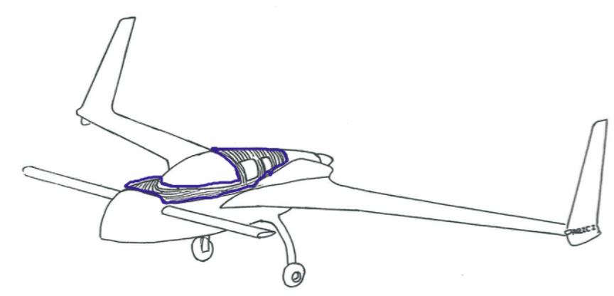
Step 6: Installing the Hinges: I pick up here with Ch 18 Step 6: Installation of the canopy hinges per plans, they just have to be positioned on my longerons. Photo to the right shows how I did the alignment similar to others. I did it dry and verified the compromises required to get good hinge bolt engagement with the longerons, while keeping good hinge alignment. I used the straightedge and very carefully aligned the edges of the cutouts for each hinge pin "grasper" to the edge of the angle iron, on the presumption that this edge is well aligned with the actual pin axis. This allowed me to keep the straight edge away from the more rounded portion of the hinge and I didn't have to have a long hinge pin reaching through both hinges simultaneously. This was an alignment judgement on my part and when the canopy is completed I'll come back here and say whether it worked for me or not. - after canopy completely installed and bolted down: This worked just fine. My hinges run very smooth. Once the hinges passed my dry alignment criteria, I marked the longerons so I could return with floxed hinges and bond them with a wet alignment the same way again. The hinge plates and longerons were then drilled and the bolts installed per plans. Oh yea: I also followed the plans duct taping the longerons and IP and F28 as shown in the photos but added 1 layer of tongue depressors (big popsicle sticks) to give a better spacing for a deflecting canopy seal per guidance from Vance Atkinson when he visited. As a reminder, when I fitted the canopy with the TB the way I liked it at the end of Ch 18 Part 1 (different website page) I marked where the canopy crossed the IP on the 0.25" spacer block which was taped to IP on both sides. This made re-aligning the canopy really easy anytime it had to be removed and re-installed ... until it was bonded in place with this alignment. Then I could remove the spacer blocks (see further down for this). |
View of alignment method for canopy hinges: Long Aluminum angle as straight edge and carpenter's square blocked against the Instrument Panel.
|
|
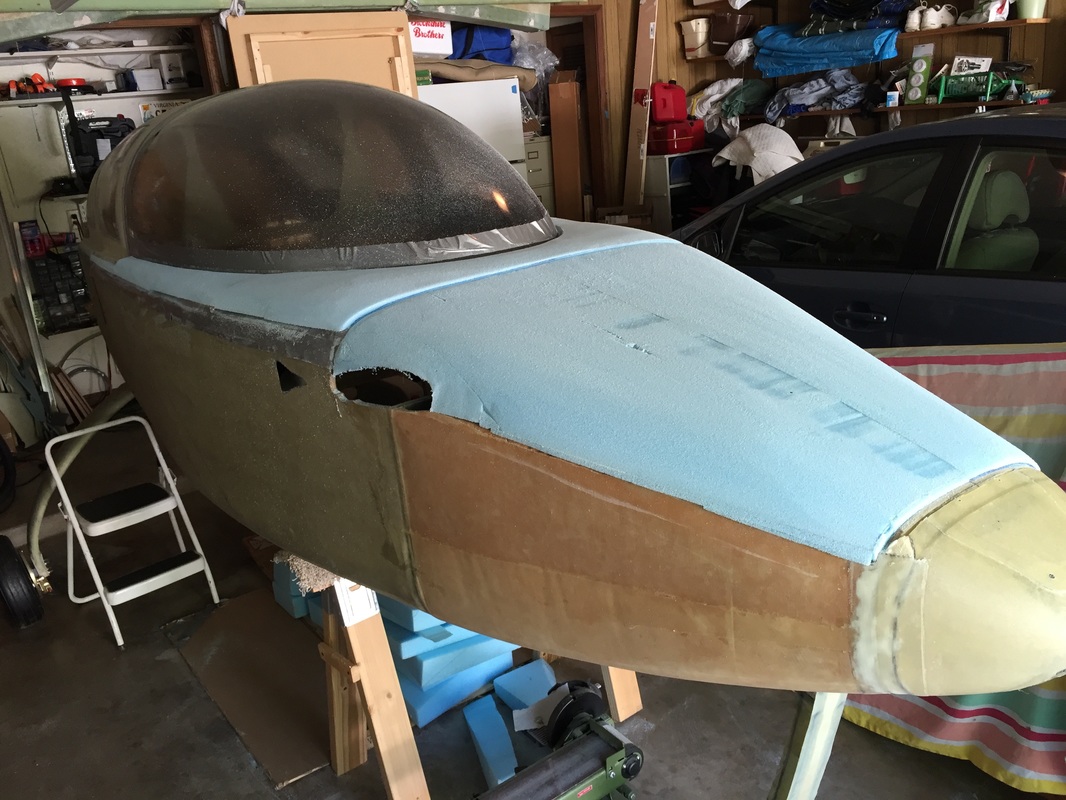
Shaping the Nose Top and Canard Cover:
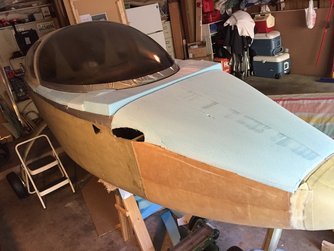
This is documented in Ch 13 since it's associated with the Nose, but note that it was done in conjunction with my shaping and building of the canopy frame. I built the nose top, canard cover, and canopy frame all from left over blue wing foam because I find it easier to work with than the urethane foam. It's slightly heavier, but much firmer/stronger, and I'm less likely to take too much off. I'm including a picture here (See Ch 13 for the progression) so you can see how the canopy frame foam was derived from the more forward foam pieces from Ch 13. Note: the Canard cover is actually called out in the plans in Ch 24 as a finish piece, but i associate it with Ch 13 Nose top and built/shaped them together as one foam piece. |
Nose top and Canard cover rough shaped to get ready for Canopy frame foam shaping...
|
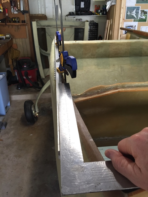
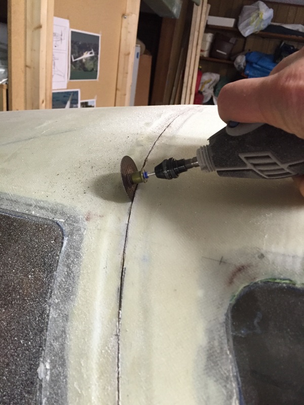
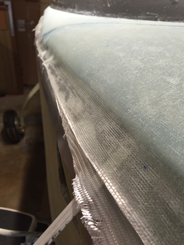
I waited until I had the nose shape pretty close, as shown above, and had rough cut all the foam blocks for the canopy frame before actually bonding and glassing the canopy to the TB. The reason for this is that once the bonding was done I wouldn't be able to get in the fuselage or adjust anything with the canopy until the frame was glassed on the outside and I make the TB cut between the windows. I wasn't sure how long this would be, so I was postponing it until I absolutely had to bond it. I was now at that point. So I removed the canopy and did all the duct taping required and removed the white tape and roughed up the 3/4" edge inside and out per plans. I only used 2 layers of Duct Tape as I was struggling somewhat to make it behave well in the curvature while maintaining the good edge where the glass would meet, and not pull off the spraylat... I thought I had sufficient grinding protection with 2 layers, but I need to be extra careful with the Dremel at that stage later, not to cut below the top duct tape layer. Then back on the TB for a last fit check and then I bit the bullet and floxed it (remembering to have the support blocks on the IP for the front end and using a screw on each side to hold the canopy tight against the TB (like Bernie, I don't like Bondo). The next day I 3 Ply BID'd it to the TB as required. I didn't build the little fill in on the top yet since my depression there is pretty small and I'll get that done when I'm in the finishing stage and will have sat in the cockpit and have a better feel for how much sky I want to block with it vs using one of those moveable sunscreens I've seen on some other Cozy's. A little detail on the rough cutting for the forward most canopy frame block since it was pretty interesting and I liked the way it came out: First, I needed to measure the curvature of the curved profile of the front of the canopy, which was easy by transferring it down to the cover board I'd installed between IP and F28 previously using a square and marking where it touched the board while vertical with the canopy edge. I then measured using the same square from the vertical to the tape line to get the inward offset at each of these points. I transferred the marked points from the board onto paper template and then marked the template with the offsets. This paper was then cut on the larger curve (which was then transferred with Sharpie to the foam top face. Then the offset was cut out and the bottom foam curve was transferred. The fit was really nice. Not perfect, but quite good and it could be micro'd with only a slight leak through (make the micro a little thicker next time). The other pieces of blue foam were shaped more approximately since they didn't have as much curvature. I'd get rough dimensions, hot wire cut them, then I typically used a small curved hand grater to get them to fit well with the lower edge of the canopy. I didn't bond anything (including the front piece mentioned previously) until I had all the blocks made and fitted to the canopy, then I micro'd them all together and to the canopy at once. I was a little unsure whether they were going to be bonded well enough because I didn't do a continuous bead of micro (spot micro'd about every 8 inches because I didn't have good access to the bottom edge of the canopy with all these fairly long blocks). I was happy the next day when I hand tested each block to see if it was firm enough to sand and they were. Now started all the canopy frame sanding. I did this with the nose top piece in place to allow me to carry it's tangent angle back into the frame (it had very little curvature at F-28). This took many passes, and since the nose top and frame really flow together I worked on them together to get a nice smooth shape. Unlike the early work on the nose this was done with the canard removed (garage space claim for car) but this proved to be good because I could see where I was allowing the foam on the upper part of the canard to bee too wide to make a good transition to the fuselage and canopy frame and could fix it easier without the canard in place. I worked on all the foam shaping for about 5 days with sessions of about an hour in the morning and evening and I thought this worked well for me. After an hour, I usually needed to back away from the job to make sure I didn't take too much off and come back with a fresh perspective to see where more work was needed. When I was finally happy enough with the whole thing, I marked the joggles (fwd cut line and F-28 and used dremel with router fitting and 5/8" grinding stone to cut the 1/16" depressions. I practiced on spare foam first and this was a great method for me. I cut the pattern for the overlapping glass plies using Peel Ply which would lay more closely to the curved frame than paper. I'm now ready to do the glass work for the frame and will post when it's done. |
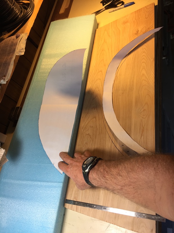
Paper template for the top curve of forward piece of canopy foam (behind F-28). You can see the offset curve strip I've cut off after using the larger curve to transfer markings to the bottom of this same piece of foam.
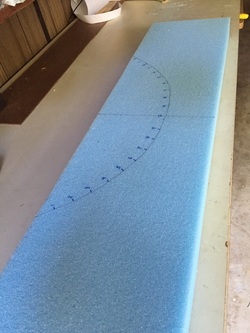
Marking the forward frame piece for hot wire cutting. This is the bottom curve, and the top curve is offset appropriately aft and inward to mesh with the slope of the canopy. This cut was not too tough after having done the nose pieces as we were well practiced, even though we were moving at slightly different speeds on each side.
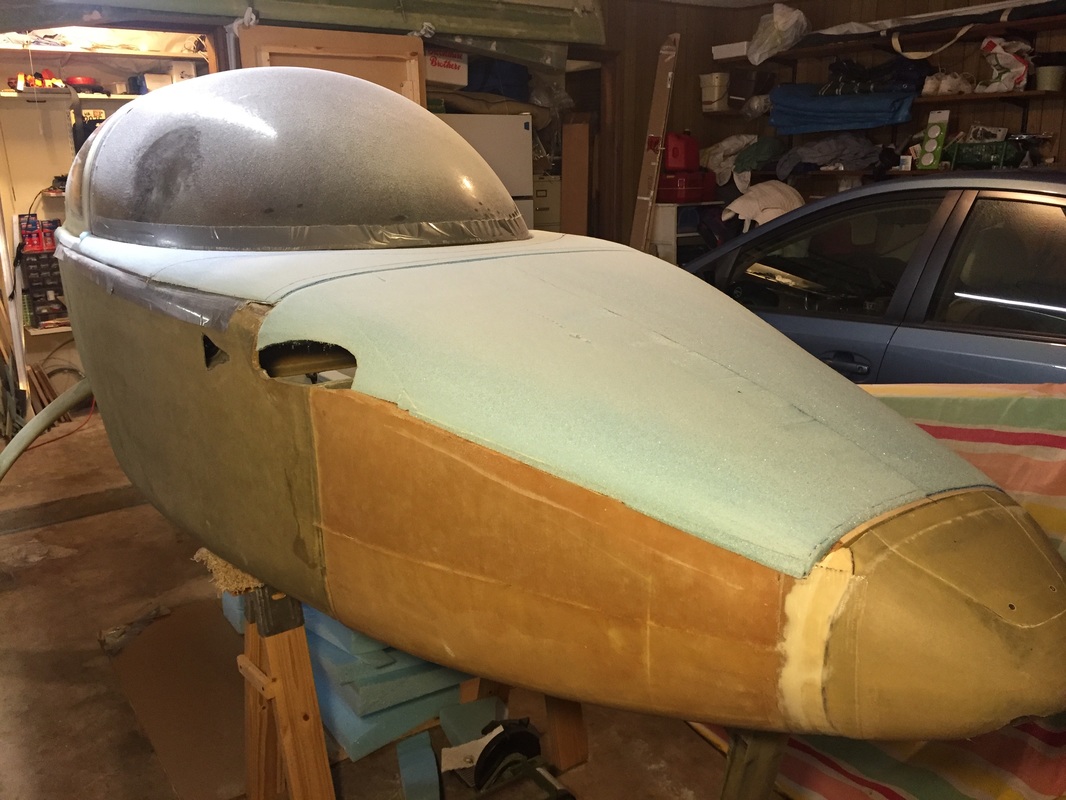
Start point for shaping the canopy frame...
An intermediate state of the canopy frame shaping...
Declaring shape good enough. Now get the joggles in, and put the blending foam pieces back by the TB per plans.
|
|
Glassing Outside of Canopy Frame
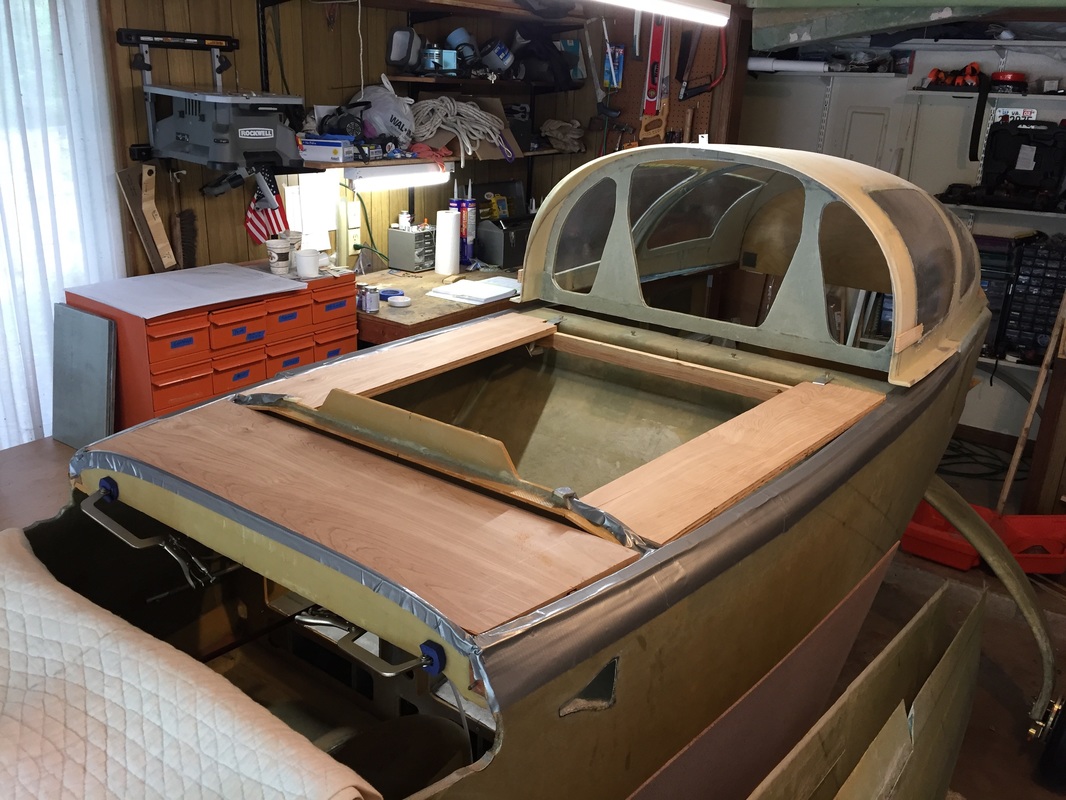
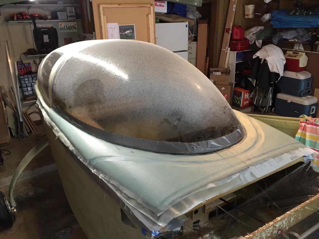
Well, after 2 weeks of refinement on the foam shaping for the canopy frame and nose top, I finally felt I was ready to glass the outside of the frame. I had to re-do the joggles because when I removed the nose top for the last time I realized I needed to take the foam down a little more on the center and Left side (looking forward) to really have the shape balanced. This was much easier to see against the F28 top. I'm leaving a slight arch to the centerline of the fuselage because I think it looks a little better. It does mean that my frame glass will not come flush with the top of F28 at the joggle, and I'll have to deal with that later, potentially with a small foam piece. Leave plenty of time to do this glass job if working by yourself. I planned for 4 hrs and it took me 7. I'm meticulous, but I don't believe I was wasting time. I was glassing from F28 all the way back to the TB cut line (remember that I've got a small piece of spacer foam for my TB tilt that needed to be covered, so each side required a main frame ply, plus approximately 15" of extension (for the BID) to reach this point. With 2 ply BID overlapping each ply on alternating sides of the centerline this was 8 separate pieces of cloth. I pre-wet each of the long forward pieces on pallet wrap (using my peel ply pattern under the plastic to get the glass set at the right shape during wetting. Transferring this long wet layup requires some confidence because it never lays right the first time and once you get that first BID layer down, you don't want to be puling up on the upper layers if you can help it. I always worked by getting the edge next to the canopy set first (all the way back) and then by hand worked the ply down even. I couldn't do this with any tools that were as good as my hands (with nitrile gloves on). I also found that I could not get the first BID layer to lay well against the fresh micro on the foam without brushing a little extra epoxy on. I think this is because I'm used to squeegeeing the micro pretty thin and into the foam so the pre-wetted ply just doesn't have the "stick" that it needs without a little extra epoxy. I believe this is a good compromise though because I don't see micro leaching up into the glass. Like others, I put plenty of flox in the gap after wrapping the first BID layer down the foam gap and back up against the canopy bottom edge prep, though I left this fill a little low rather than have it be too high. I'll fill the slight depression later with micro. So why did this take 7 hours if I thought I was really ready to go?
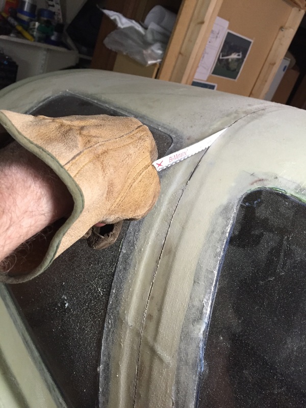
I don't see a big place I could have saved a bunch of time. If another builder sees where I could have been faster, email me. I'm always ready to learn. Anyway, it's done, and I think it looks pretty good. It still has a couple of little bumps but I think I'll be able to manage the finishing well. I don't see any bubbles as I leave to cure (picture). We'll see in a few days how it cures out. 4/24/16 I waited 3.5 days to cut the TB and during this period built the frame for turning the whole thing over on the floor and gathering stuff I'd need later in finishing this chapter. I followed tips from other builders to insure good support along the length (not just at 3 points, per plans) to avoid sagging. When I cut the TB I used a Dremel with 1.5" cutting wheel to cut through the TB along the cut line. This wheel is not big enough to reach the drip rail so I didn't have to worry about inadvertent cutting too deep (though I did stop a couple of times and check with a flashlight from the gap in the firewall...). I then used a hacksaw blade by hand to cut through to the drip rail since this blade can't cut through at it's rounded tip. I then used the same hacksaw blade as a releasing shim along the sides between the glass and the duct tape - this took about 30 minutes because the bond was pretty good to duct tape, and the shape is curved so you need to be careful. Then I did the same thing with the blade to get a release gap where I could not get the duct tape out of the drip rail back when it was cured... Then the whole thing released pretty easily with slight pressure from below between F-28 and the IP and then again at the top center of the TB cut line - reaching up through the gap in the firewall. Be patient. I think mine came loose easier than some because I'd carefully done the blade based release from the duct tape first. With the wood frame bondo'd to the frame and cured for an hour, Reece helped me lift the system off take it out of garage, flip it over and return it to the garage floor. I need a Siu dancing banana imogi here! |
Ready to star the Micro (5:30am)...
Side view before starting the glass job: foam looks good.
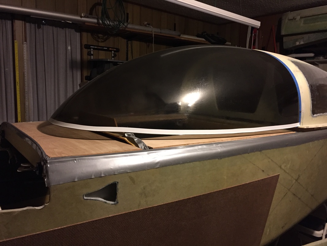
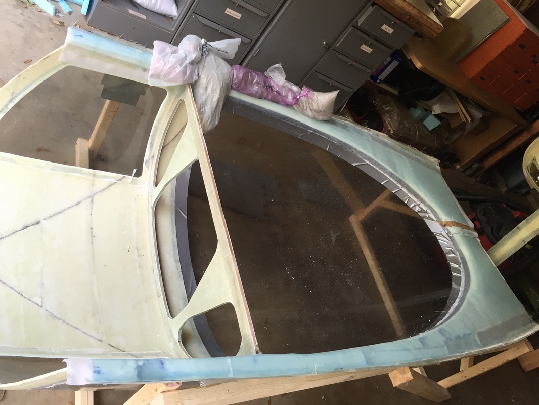
Finished glassing and peel ply. Yea!
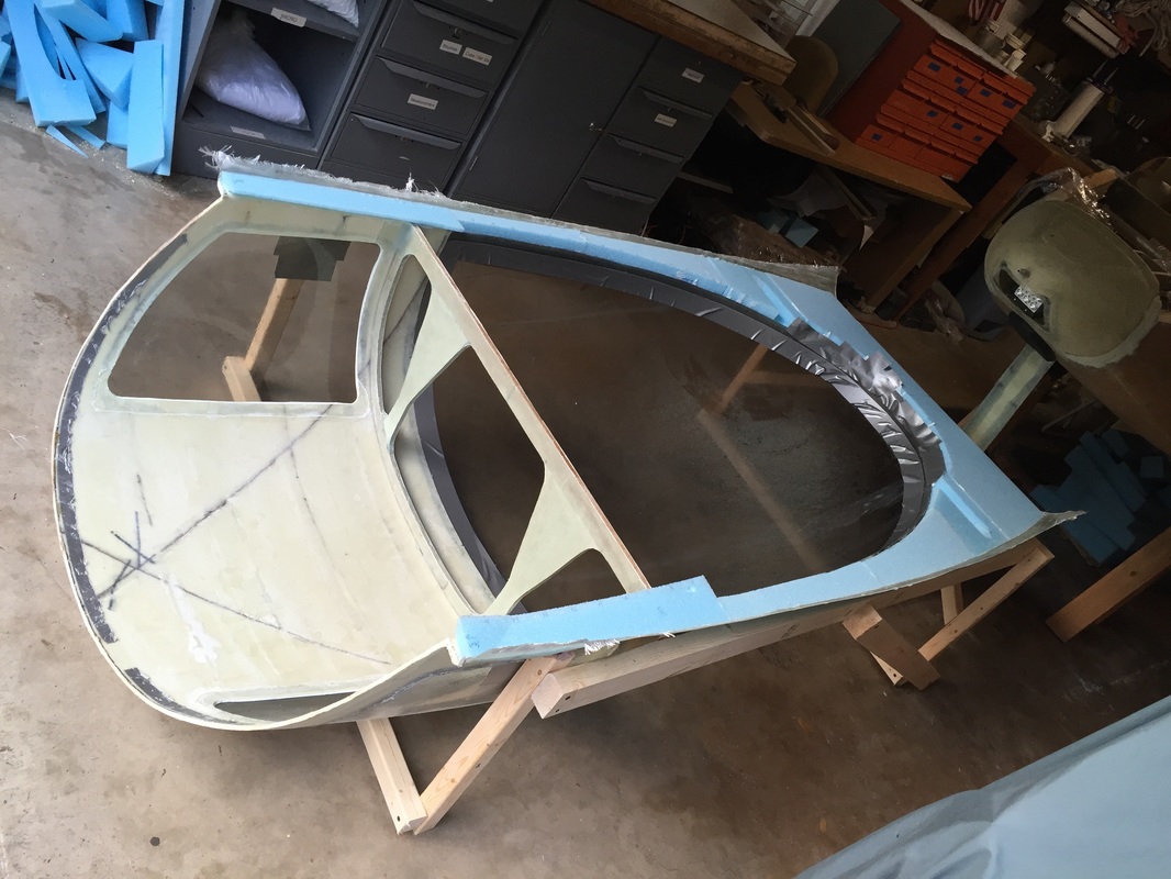
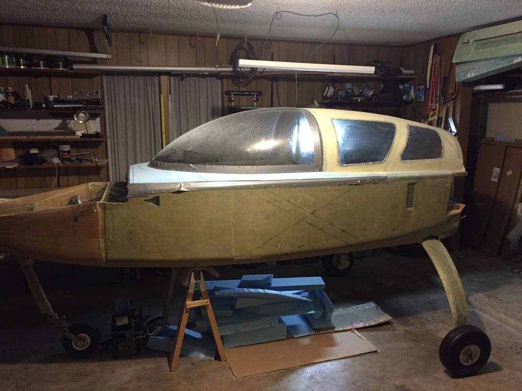
TB/Canopy cut off and inverted for more work
|
|
Steps 12-13 Hardware Reinforcements and Inside Skin
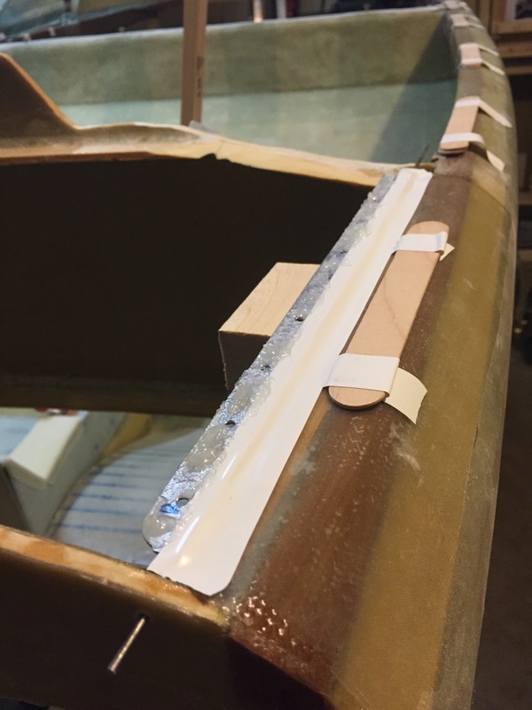
Now that I have the canopy on the floor followed plans for reinforcements and inside skin. Notable elements on this were getting a nice smooth transition from forward of the instrument panel line to aft. I was a little shy on removing material down to .75 inch thickness as directed in the plans, and my upper surface started about 1/4" higher than F-28 so my frame foam is a little thicker than it calls for. If I were doing it again, I would have been more aggressive with foam removal on the inside since the resulting structure is quite stiff, and it required a bit more shaping than I think I would have needed around the IP. Later you will see that I needed to trim down the top of the IP a little to get good closure of the canopy, and again, this could have been avoided if I'd removed more foam from the inside of the canopy frame. Note that the inside skin layups took me as long as the outside, even though I used the same process and had the experience from previous. It just takes a while, but I'm very happy with the result. Before moving on the Fuselage Top and hinges I decided to make a small rib for the canopy aft edge close to where it will interface with the TB drip rail. I'd read about this flexible edge migrating with temperature and not fitting well later. I used cardboard to trace out with Sharpie the curvature of this aft edge at its associated angle, and then used the Sharpie line to trace onto a paper pattern the .75" thick rib shape. I then used this paper pattern with the sewing marker wheel (with the little teeth) to transfer over to some .2" PVC foam I had received when I bought the project. This stiffer foam was pretty easy to work with considering how thin and flimsy the rib is before it gets 5 min Epoxied into place. Once bonded in place I used 2 ply BID wrapped around at 45 degree orientation and peel ply'd. This little rib came out remarkably stiff. I still had to deal with fit of this aft edge later as you will read, but it wasn't because this part was shifting it's shape... At the same time I was doing the rib I also inserted some 3/8" PVC foam on the main bulkhead so it would extend down flush with the front seat back when closed (remember I raised the TB an inch this winter when fitting with canopy after building this bulkhead to plans last summer). Not a big deal. I will end up reshaping the bulkhead openings to match this higher TB and the profile of the head rests when I finally build them. |
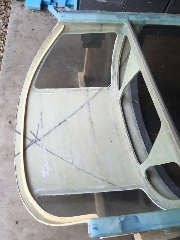
Curing inside canopy skin after hard points set. Sand bags were holding skin in corner where I had outer skin curling up (all these corners were floxed)
Foam for trailing edge rib (yellow) and bulkhead spacer (grey) micro'd
|
|
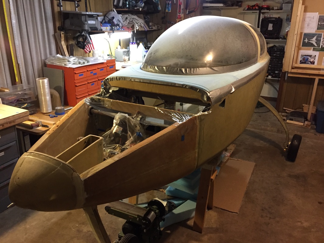
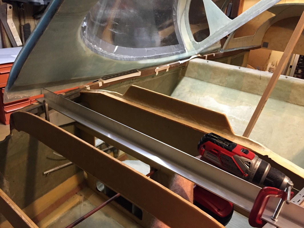
Steps 14-16 Hinges and Removable Fuselage Top
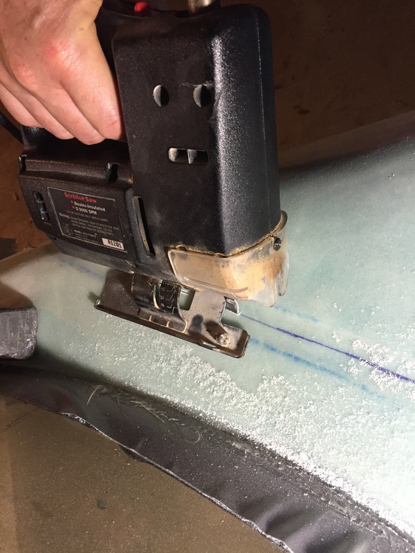
There's a lot here, but it's pretty well linked so I'll cover it together. Once the canopy frame had cured (waited 7 days again) I trimmed the big overlapping layups and moved back up to the fuselage for floxing the upper half of the pivot hinges. This involved re-checking the alignment of everything just as was done before glassing the canopy outer skin. Because I'd marked it well and used the laser, this went really quick and was then double checked with ruler measurements as before. I followed the plans for having this set and before removing it to drill and bolt the upper hinge plates, I completed the Fuselage top activity as shown below. I actually had to remove the canopy a few times to check things, but just pulled the pivot pins for this. Several key activities beyond what's explained in the plans involved refinement of the trimming around the floxed corners, and preparing for cutting the Fuselage Top (FT) from the front of the canopy frame. I've included a picture of the aluminum angle I used to position/flox the FT hinge plates to the new longeron doublers. I used the bondo'd block method for flowing the upper part of these hinge positioners to the bottom of the FT before cutting it from the canopy as described in the plans, and it worked great. I used 2 rivets and a clamp during the flox stage and once everything was cured, drilling and riveting was completed. I followed Andrew Anunson's tip for using electrical tape to mask the hinge during floxing as it's easier to release when the flox overlaps it by about 1/16" to 1/8". The one other thing I did that helped was drill a 1/8" hole aligned (by eye) with the hinge pin line in the top of F-28. This allowed me to quickly insert/remove hinge pins without reaching into the cockpit for the on/off iterations associated with the FT from here on. This will not work once I have the nose top glassed in, but it's nice for now. With the FT now positioned, it's time to bite the bullet and saw the cut line between it and the canopy frame. This turned out to be easier than I expected. I just marked the center of the joggle again, and followed the line with the jig saw set to 45 degrees (accept in the transition up from the longerons). I just did the transition by eye and it came out fine. You do need a long blade for the jig saw (or at least I did with my thicker foam... After this, everything goes back on the fuselage so the sawed gap can be opened up to 1/8". THEN back to the bench and the canopy jig to micro/glass and trim the sawed faces of both parts per plans. The result is the canopy starting to look really cool (see pic below). Can I have another dancing banana imoji? 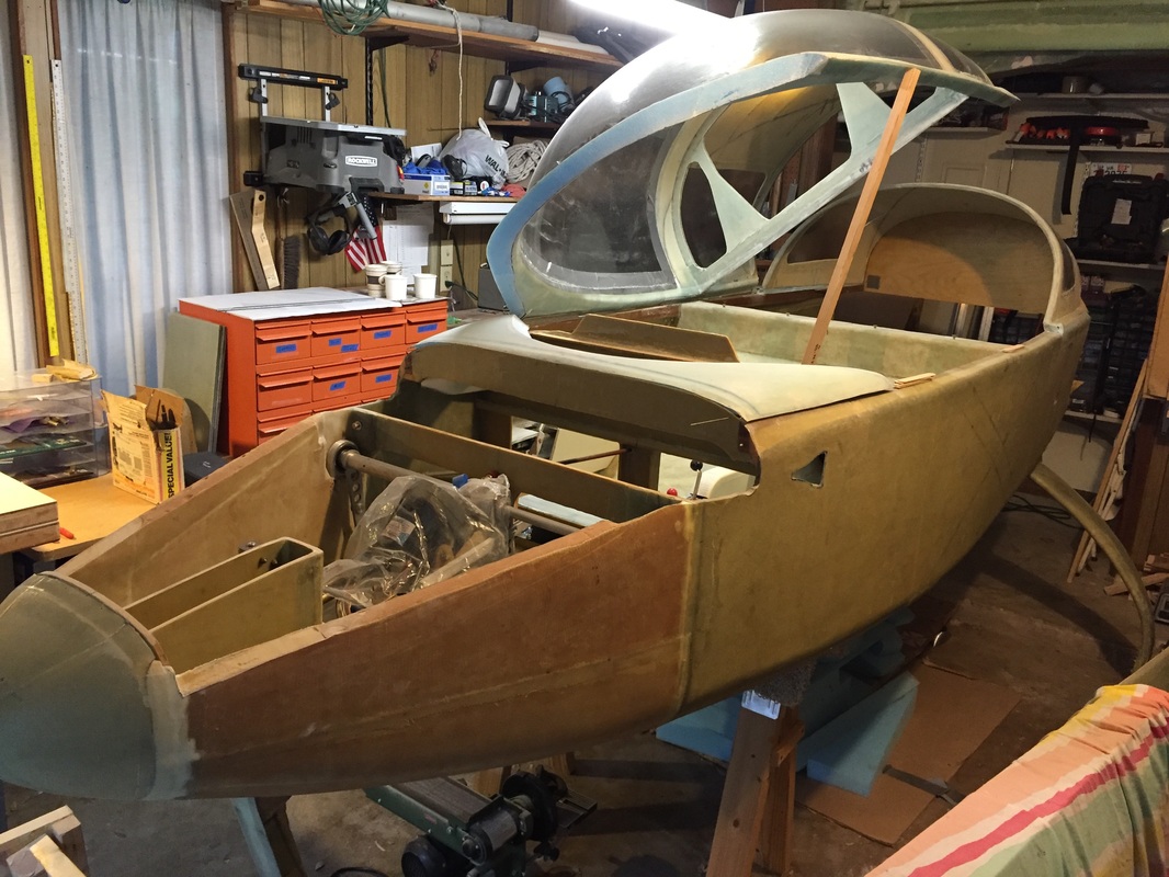
|
|
See Part III of Ch 18 for continued work after this stuff...