CHAPTER 18.1: Turtleback
|
|
|
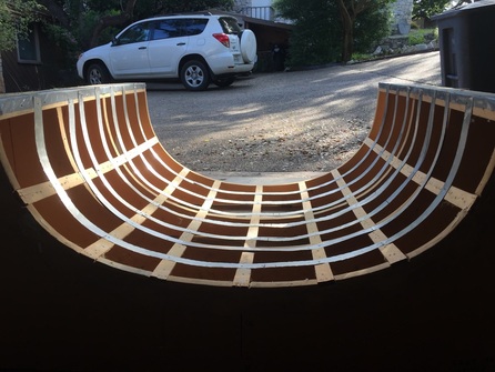
Step 1: Turtleback JigBen Bennet loaned me the turtleback (TB) jig as we are building to the same size 38.5" wide canopy. We ordered canopy/windows together with Nelson Amen from Todd's Canopies to shave on shipping. The canopies came wrapped well in packing and boxed to prevent damage. I stored my canopy since I'm the last to use the jig and had plenty to work on in Ch 13 when all this was going on. When the jig was available and I'd gotten to a good stopping spot on Ch 13 I started to re-furbish the jig. The shape was good but as you can see from the picture on the left, the aluminum strips needed attention. (Note from when I finished with the jig: removing the TB from the jig the first time can be tough on these aluminum strips if you have any epoxy get through the foam seams - which I did. The next person to use this jig will have to refurbish just like I did, but it's nothing compared to building the jig in the first place). Thanks Ben for loaning it to me!
|
Step 2: Inside Layup
Hicks' Hinge Method
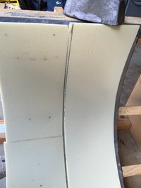
Using a weight (top) on each flange to hold foam strip into jig while marking and later securing it with drywall screws
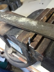
Filing tip of drywall screw
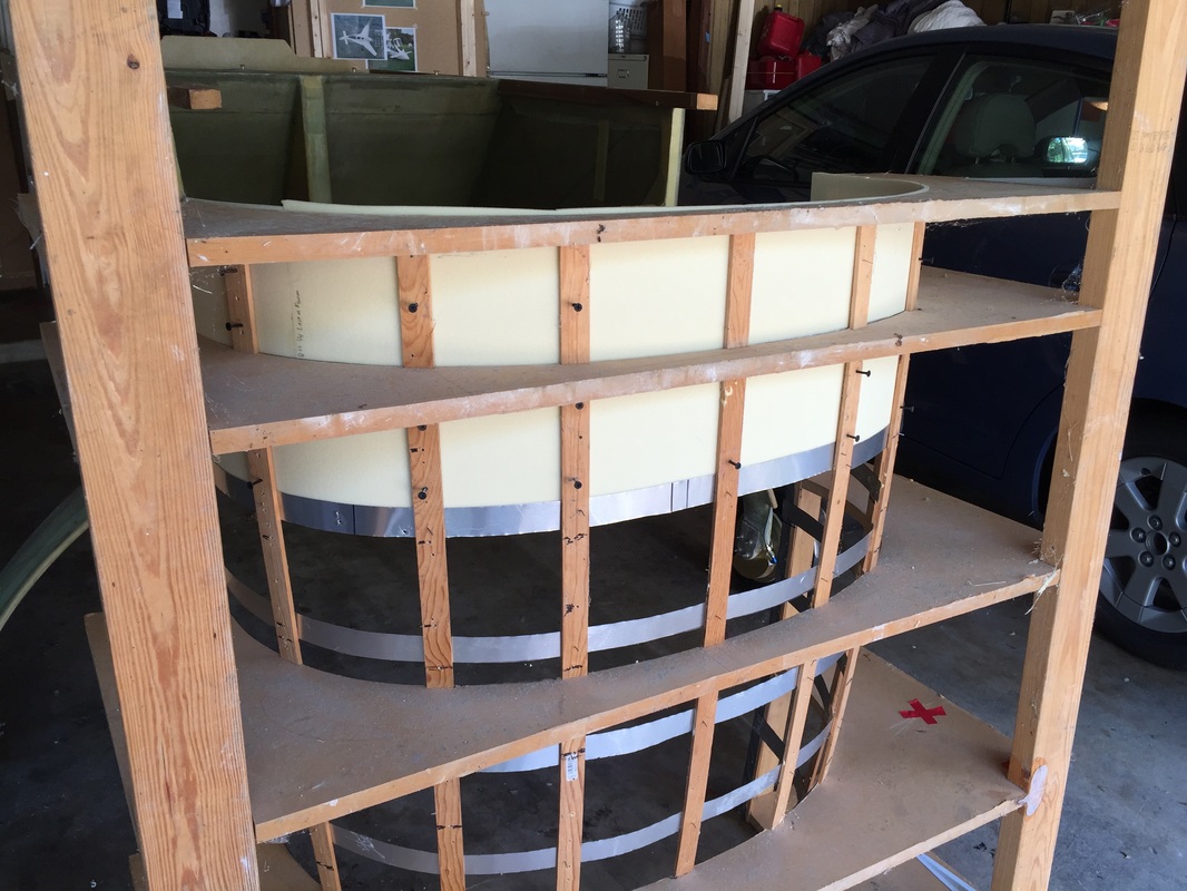
Inserting drywall screws on bottom
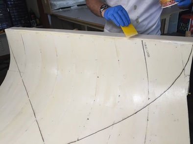
Finishing Micro Prep
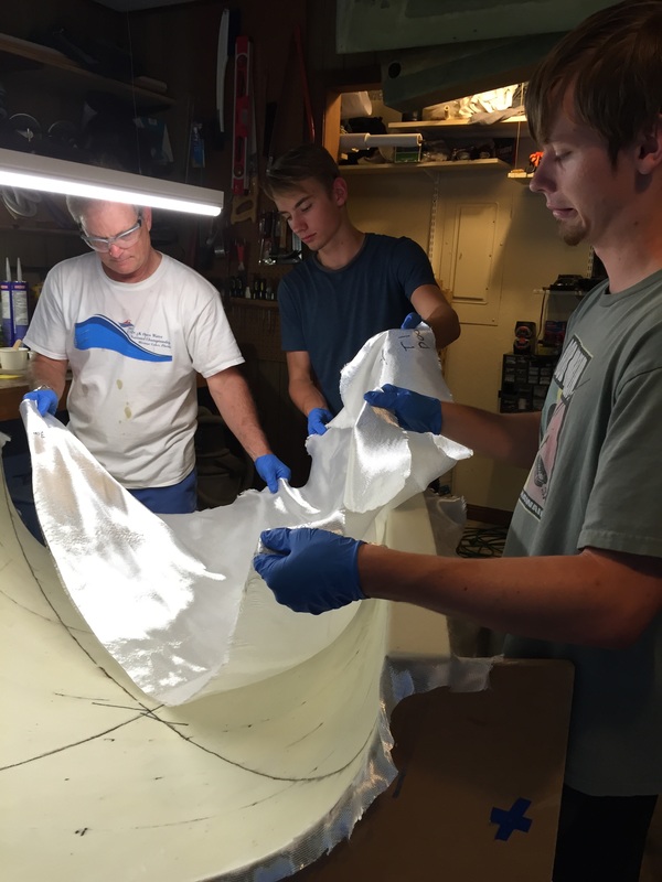
Starting the layup...
|
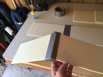
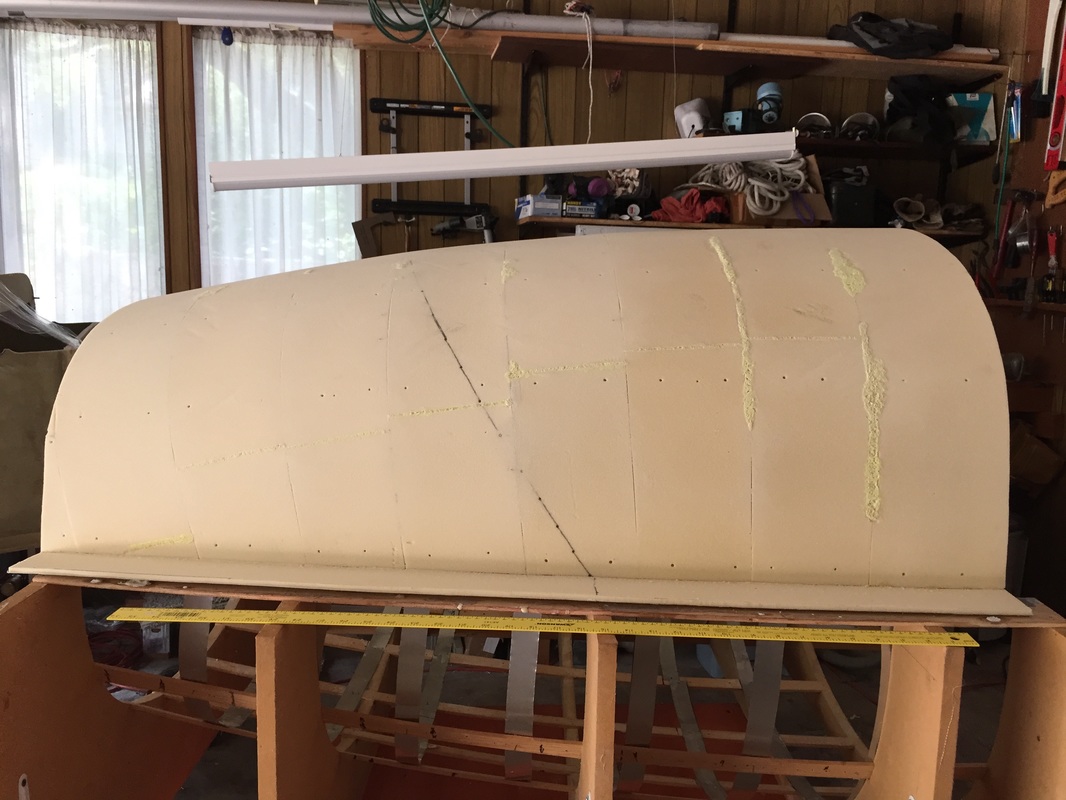
I followed the plans and used Wayne Hick's hinge method for building up the foam strips to lay in the jig. It takes a good bit of patience to get their shape to match up, but they sand easy with 200 grit and would mark them as shown to the left and then sand to the mark. This was not a one step process but probably took me 2-3 iterations to get the fit good. All my joints were not perfectly tight, but there were no gaps greater than 1/16".
I held the foam in place using weights on both ends (resting on the flange of the TB jig) while I inserted screws, once I like the fit of each strip. I screwed the sides where I had access with the jig on the ground, and then turned it up to get the bottom, then back down for the next strip. I filed the tips of the drywall screws to eliminate the sharp tip and maximize the gripping thread into the foam. I only took about 1/16th off the tip with a hand file but this allowed me to feel when the screw was coming through the foam without puncturing my finger as well. I let all the screws be flush with the inside and they were no problem unscrewing after the inside was done. This is a fair amount of work however, I counted 130 screws that I spent about 20 seconds filing on each... as I went along. When all done with the foam strips and glueing the flanges on per plans, I used masking tape to seal off the few joint sections where I still could see 1/16" gaps. I had read and talked to others about difficulty getting the tape to stick, and what I found was that the masking tape would stick fine for about 2-3 hrs but if I left it over night (summer time, uncooled garage) the edges would peal back. I resolved that the taping would be fine, but that I needed to tape it and then get started with the micro, layup,... The only thing I varied was taking the 1" wide masking tape and cutting it lengthwise into strips about 18" and 1/2" wide. I figured this would reduce the surface area that the masking tape was blocking from direct glass/micro/foam adhesion while still providing enough area to seal off the 1/16" or less gaps I was taping. This may have been overkill on work since I was using scissors to cut the tape. A better investment in time would have been to tape ALL the seams. When I removed the TB from the jig it had some trouble (described next paragraph) due to epoxy seeping through extremely thin gaps (not the big ones that I could see) and touching the aluminum strips in the jig. I had help from two of my sons with this large layup which was nice given the 88 degree temperature in the evening when we set about getting the inner layup done. We had all the pieces of UNI pre-cut and fitted dry in the jig to make sure we could focus just on alignment and wetting out once we got started. I did the micro work on my own, and quickly learned that I needed to work fast and used the squeege with 80-100 gm batches (I don't like making batches of epoxy any larger than this, to insure it gets spread before it starts to set. In this case I was using MGS 335 with 100% slow hardener and had no problems what so ever. Once spread, this slow hardener will take several hours to set. 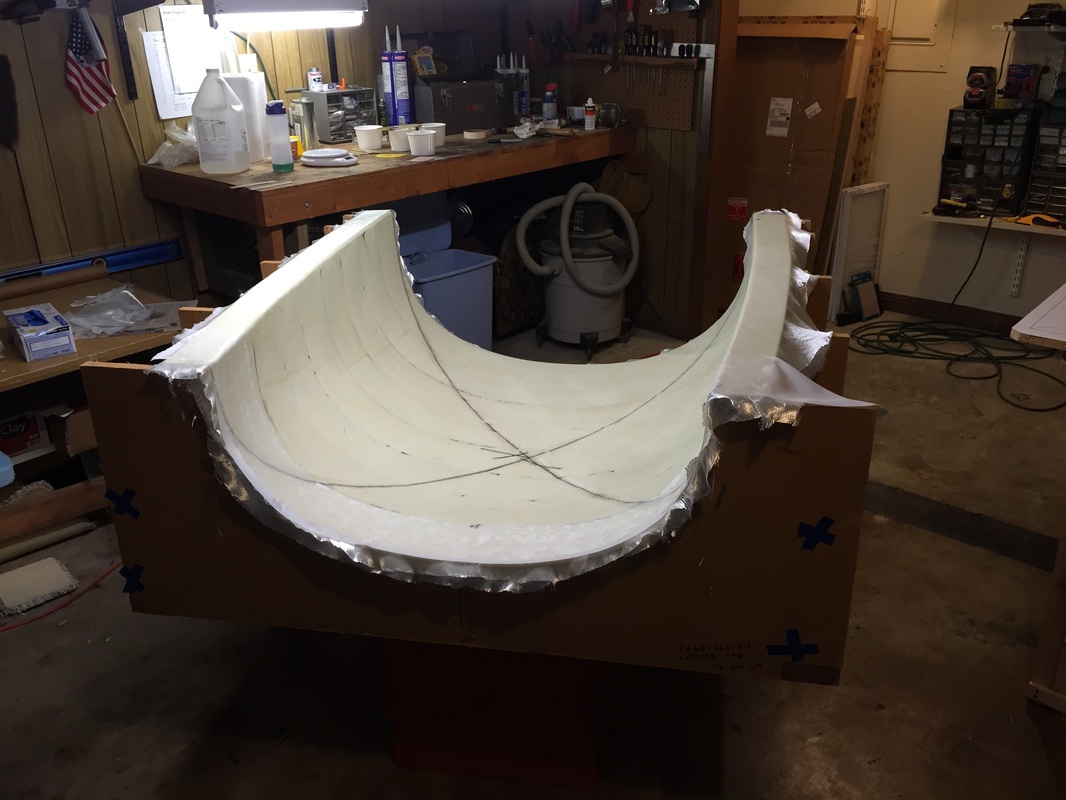
Layup Complete, starting peel ply of whole thing (this takes a while, given all the curvature...)
|
Step 3: Bulkhead and Drip Rail
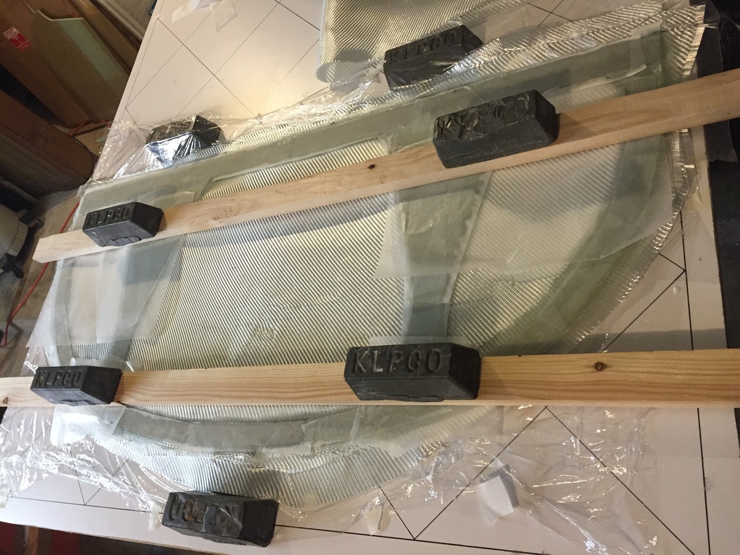
Flattening the bulkhead during layup
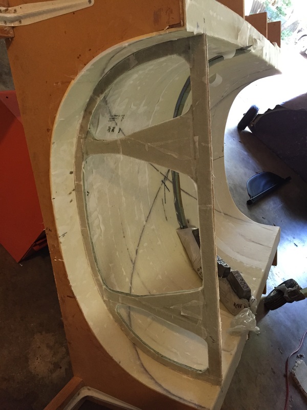
Bulkhead fitted but not taped yet, and 3rd section of drip rail curing. Note tilt of jig to allow sand bags to press on drip rail during cure.
|
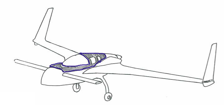
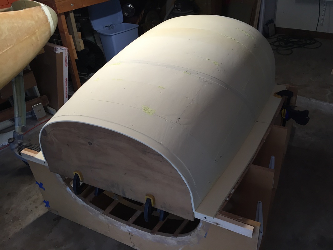
I followed the plans for the bulkhead and merged various pieces of 3/8" foam since I don't have a lot of this at the moment. Even though my turtleback is wider than the plans, the center supports still go in the same place as the seats haven't moved. I traced the turtleback outline onto the assembled foam to have a good match by setting the bulkhead up against the big end of the turtleback while in the jig (I used a straight board across the flanges to but the flat bulkhead edge to, and had someone assist me holding it while I did the trace following the inside edge of the glass that I'd already had cured on the inside of the TB.
I used single pieces of BID to do the bulked layups on both sides (which consumes more material but made keeping fiber alignment and speeded up the layup process. Knife trimming was really helpful here, as it only left a little bit later for finishing the edges with the multi tool. Once both sides were complete, I started fit checking in the exact spot where it would fit in the TB and fine tuned the edges slightly to get a good fit and BID tape it in place per plans. Drip Rail: Again following plans here. I did use plastic sand bags to weight down the drip rail and insure conformity of the glass to the curves, and this meant doing the layup in 3 sections and rotating the jig for each so that gravity would help with the sandbags. I had some difficulty removing the duct tape when done, but following others, didn't worry about it since I can fix this later when the cut line is actually cut. Finally ready to remove the TB from the jig... |
Step 4 Glassing Outside of TB
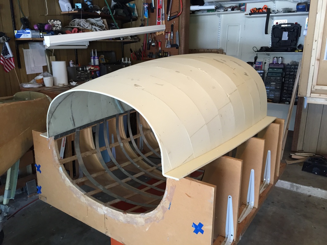
Yea! it's out of the jig.
The UGLY! - masking tape ALL the interior seams...
After Good Stuff substitute and some sanding...
Final sanding done, including depressions fwd and aft and at cut line and better fairing where foam repair had been done.
|
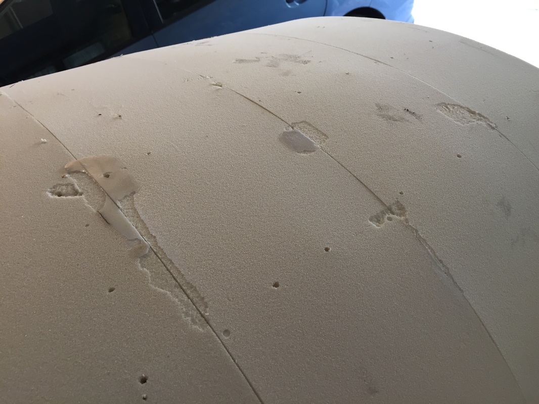
Removal from the jig was not easy, as I'd gotten some epoxy leak through at foam seams in a few places. In most areas it released with a more deliberate pull upward from the flanges, but you don't want to over stress the flange! In the worst spots I used a stiff putty knife (1.5" blade) sliding between the foam and the aluminum strips to get release. In one spot the epoxy had spread over the under side sufficiently that I had to tap with hammer on the handle of the putty knife to get release. Once released, I could see the problem. I again returned to hints from others which lead back to Wayne Hicks use of dremel to carve out the epoxy and re-fill with pour foam. I got some advice that using "Good Stuff" aerosol foam would work in place of Pour Foam, and since I had some I used it. THIS WAS A MISTAKE. The Good Stuff foam is more elastic and when you sand the outer surface it depresses and then releases back when you remove the sand paper. Most of my problem areas were where the Windows would be, so I smoothed out the foam overall, and then did a little more local removal of the Good Stuff with sand paper and my finger. The result was OK, but not great when the outer layup was completed. In some places I had not carved out enough of the Good Stuff and it gave the glass a slight rise. I'll now have to deal with this in the final contour and finish phase...
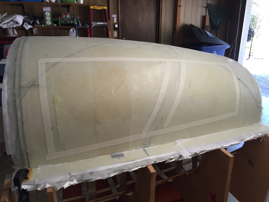
Completed outer layup. Not trimmed yet, but started layout for windows (next section)
|
Step 5: Windows
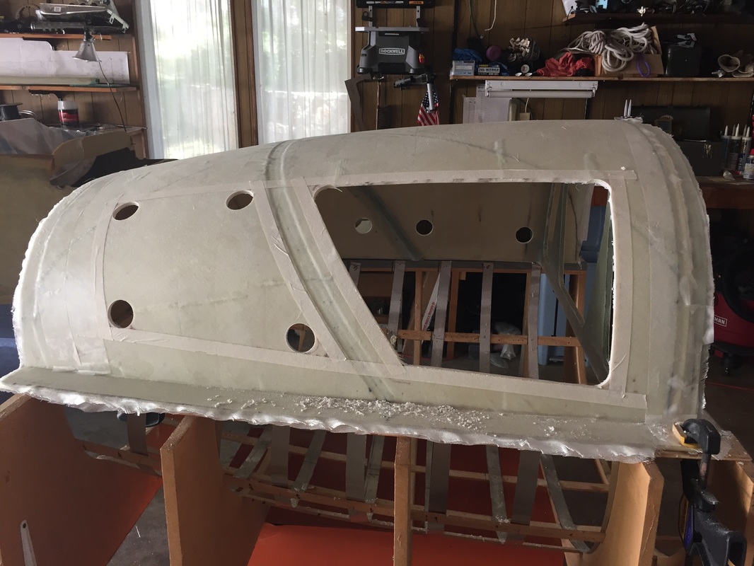
Cutting the window openings (first the corners, then the sides)
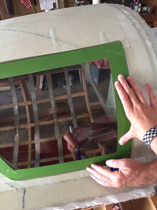
Marking the window opening on the inside of each raw window piece from Todd's (sharpie in my hand on the inside) - This image also shows the worst of the dimples that were caused by the elastic nature of Good Stuff in the foam repair- above the window - follow Wayne Hick's method with Pour Foam to avoid this problem, which will give me more work in the contour/finish phase...
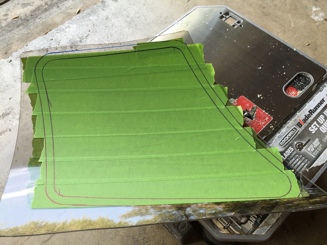
As-recieved window from Todd's, marked with window opening (inner contour) and marked with 1/2" outer offset to trim away excess plexiglass.
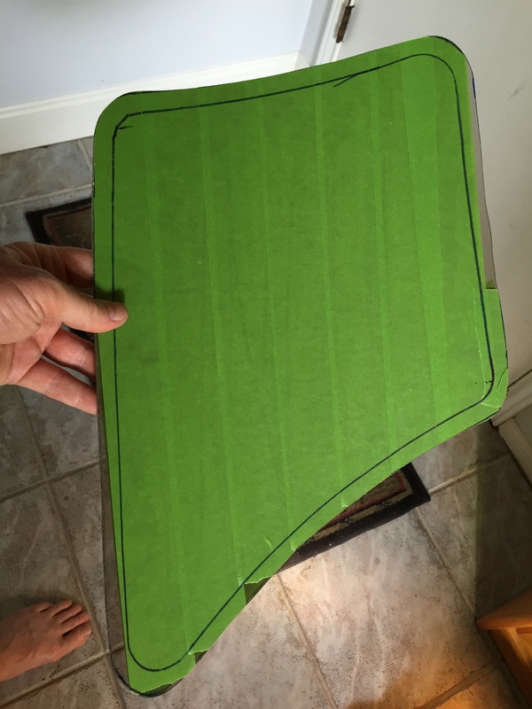
Excess plexiglass removed: now will razer blade the inner contour and remove all masking around the 1/2" perimeter.
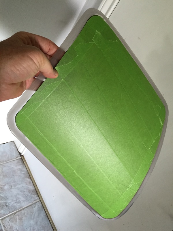
Window ready to be installed: perimeter is roughed up with 200 grit sandpaper and window is masked inside and out to protect the viewing area.
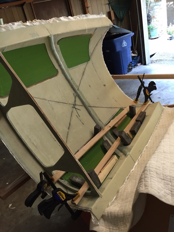
Using clamped boards with wooden wedges pushing on window centers and weights on the window perimeters during flox process.
Once the trim pieces (see photo to right) are micro'd back in, I needed to micro fill the gap all around each window on the inside between the window and the inside glass skin. I did this by making very thick micro (that would not run but still looks shiny) and troweled it into the gap after 1) spraylat the window for thin layer protection everywhere, and 2) blue masking tape around the edge that I wanted to preserve as the visible edge of the window. See picture below.
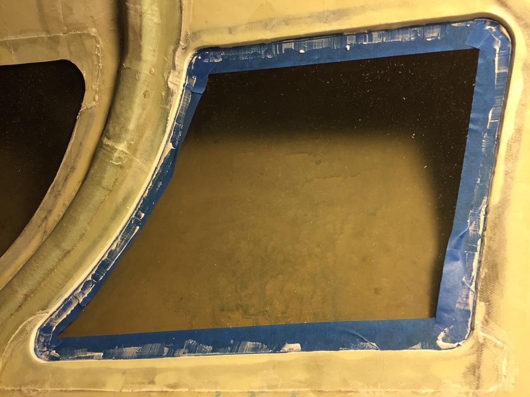
This looks ugly on the masking tape and that's OK, as long as the fill bead looks good because... after 3 hrs (I was using MGS 335 with 50/50 fast/slow hardener) the cure is just getting to the knife trim phase and you just very lightly razor blade the very edge of the masking tape where it touches the micro bead (see below) and lift off masking tape and spraylat cover (see right) for a nice edge. Then re-apply the spraylat. I just use a paint brush because I can't get spraylat to come out of a hand sprayer nozzle...
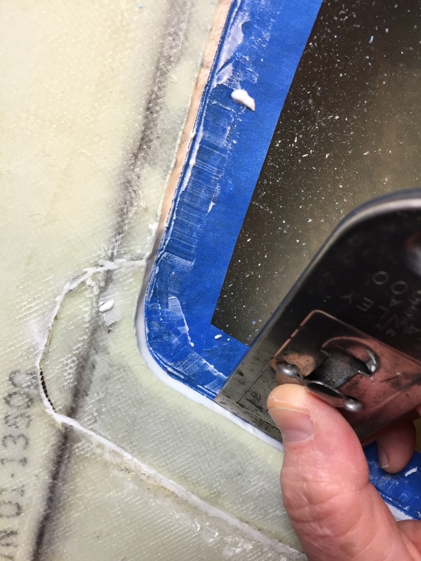
|
I wanted to have as large a windows as I could while still following the "lines" of the Cozy MK IV so I started by positioning the window pieces from Todd's Canopies to see where they would best be positioned. I found that the slant angle of my cut line was not the same as the slant angle of the windows supplied by Todd's (Todd's windows are oversized however to allow you some flexibility). Once I had the tape on the TB, I did a double check that all my window pieces were indeed at least .5" oversized to this outline and cut the window holes following the method of Siu (hole saw in corners then multi-tool the outline). I then masked all the window pieces completely (green Frog Tape) and had someone press them against the outside of the opening while I traced the opening contour from the inside on each window. I then offset .5" another contour outside this to be the profile of the actual window. I cut this outside contour with my table/jig saw (a Blade Runner - which though it's not a "professional" grade system, is amazingly useful for cutting lighter stuff like foams and plastic and thin plywood). It's really ideal for someone like me working in limited space of a 1/2 garage since it's portable, and I keep it hung on the wall when not being used. I have a note about it in my Tips page. OK, anyway: Once the window outline is cut, I razer-bladed and removed the masking tape at the original inner window (marked from the actual opening as described above). I do this then on the outside of the window as well to expose the 1/2" of plexiglass that next needs to be roughed with 200 grit sandpaper on both sides to allow floxing adhesion. I then cut the strips as described in the plans on the long edge of each window opening on the Inside of the TB and got started removing the foam from between the outer and inner TB skin to create the pocket for the window to slide into. I tried several methods on removing this foam: first a little use of multi-tool with the round grinding blade (see picture) which is my most common use blade. Because the TB is curved, this made me nervous of grinding through the really thin skins I then went to Dremel with cylindrical grinding bit (see picture). It turned out for me however that the Dremel made me more nervous because it cut so fast and the teeth are quite sharp on this blade that after a couple of "jumps" with it coming out of the slot between the skins I went back to the multi-tool exclusively. It turned out to work just fine, partly because my skill level was improving and I was getting a good feel for a) what the tool should feel like as it's taking the last of the foam from the glass, and what it looks like through the glass as the last of the foam is being removed... It's also nice that the depth of the blade is just right for the 1/2" depth of the window (I did a lot more fit/checks when I was working with the Dremel because it's harder to be smooth and even on the depth with the small cutting head. I'm sure there are lots of ways to do this, but this worked for me and I didn't tear up the glass anywhere around the windows, so passing it along. Once all the windows fit well, I used the jig again to rest the TB with first one side and then the other going through the flowing process. I did this because I was holding the windows against the outer skin with the clamped board/wedge AND weights around the edges method instead of the plans Cleco method. If you have Cleco's, I'd probably use them because a down side of what I did was I didn't have good access to the outside (it was facing into the bottom of the jig) so I could not easily verify minimum depression of the window from the outer skin profile and I got some slight flox blobs on the outside where I couldn't reach to wipe. My windows turned out good because I had all the weights on perimeter nevertheless, and the little bit of flox that came out did not hamper the windows or the skin and can be easily filed off without window damage as well. Note to self: Masking Tape: I used an old role of white masking tape to do the window opening layout on the TB when I got started and it didn't come off well at the end. See last picture of previous section. I wasted 4 hrs getting all this old tape off the fiberglass by hand. NEVER use old masking tape. The new green masking tape I used on the windows (Frog Tape) worked great however and prevented any flox contamination or scratches during the installation process. I removed all the masking tape once the windows were installed, and used ACS's 4220 Plexiglass Protect film on the outside of windows and canopy, as first shown me by Berne Siu. Once I had the windows in and protected, I did a fit check with the firewall, TB, canopy and trimmed the canopy (rear edge) about 3" to fit well with the F-28 template on it's front. Now all this goes into storage until I get done with Controls Trim, and Firewall chapters... 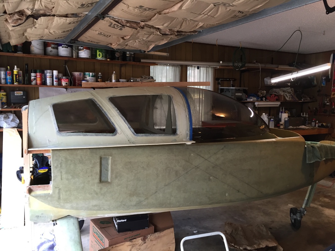
Finished install of windows, removed masking tape, and brushed on the plexiglass protect.
The canopy has been fit checked with the TB against the firewall, and trimmed to fit with the F-28 template on it's front.
I stopped work on the TB here and stowed it and the canopy August 2015 because I still had a ton of work to do in the fuselage (Ch 15-17 and 19 some Ch 24 and 12. I'm going to go to the shorthand TB from here on, sorry, tired of spelling Turtleback out. So you thought I was done with windows? Nope. I now need to finish out the inside window edges to make them look reasonable (I won't know if they look nice until the finishing stage with some paint...)
Finally ready to start work on TB again in March 2016. The first step is to get those fiberglass trim pieces back in place that I had to cut out to slide the windows in to their respective frame/pockets in the TB. Here's a picture of the TB clamped to my workbench (1x2 between the windows keeps windows from touching the workbench top. I flipped this over depending on which windows I was working on (the lower set in each case). Continue reading to the left.
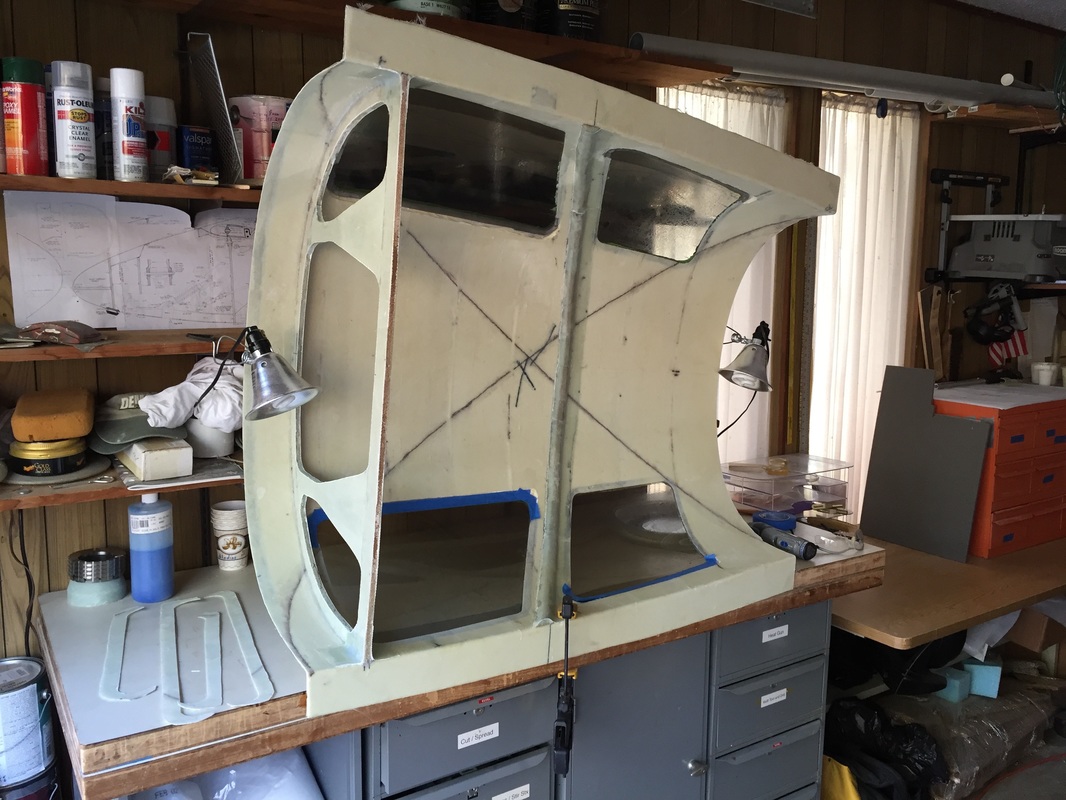
TB clamped to bench. 4 window trim pieces on the left, to get micro'd back in place.
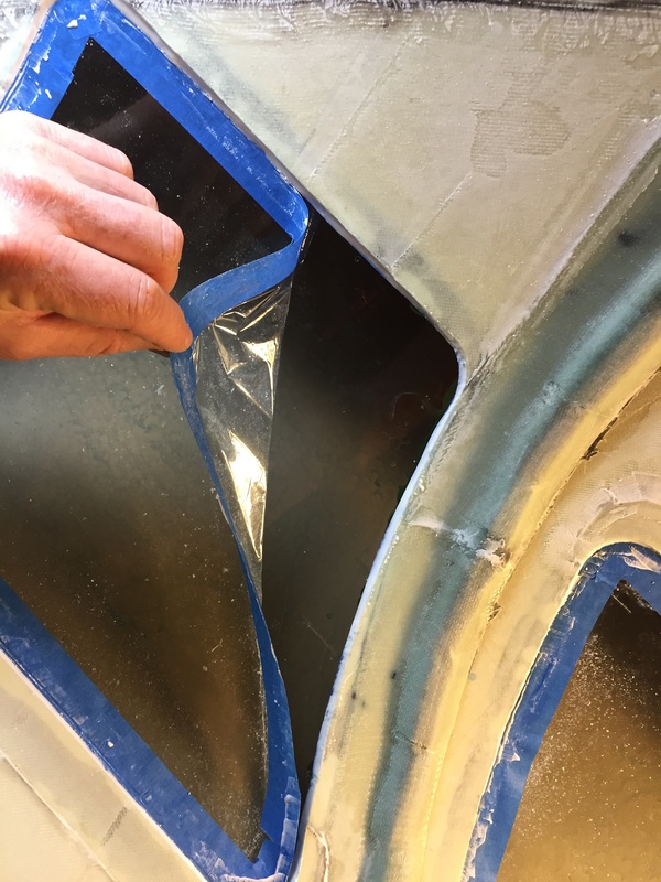
|
|
Steps 6 & 7: Hinges and Firewall:
No problems with hinges. I did the alignment using a carpenter's square against F-28 and a piece of Al angle as shown to the right, paying very close attention to where the hinges aligned to the Al angle. Did it once dry, to know everything would line up and that I had good overlap on the longerons both forward and aft, and then did it again with everything sanded and floxed per Plans. I also re-did a complete laser alignment check on the fuselage with turtleback and firewall...Looks great. Everything is aligned with reference to the upper longerons. They get leveled first (for and aft and side to side) to within +/- 0.1 degree of 0.0 with a digital level. Then the laser is set up in front of the fuselage casting a vertical laser line (it's got an internal pendulum, and I've independently checked it with a long string pendulum). I have marks on F-22, F-28, IP, and main seat back which are centered between the longerons and I get the laser aligned with all of these simultaneously. With the turtleback and upper firewall mounted (the latter grips the upper longerons) I can mark it's centerline from the laser and compare it with the distance midway between the upper longerons and these match to within +/- 1/16" (laser light beam is 1/16" wide). I also set up a pendulum on the top back of the turtleback and checked plumb line running down the firewall. This plumb line is verified to agree with the laser and the midway distances between the longerons. I then checked the engine mount hard points buried in the upper firewall and they are likewise evenly spaced from this centerline. I marked all these points and noted that they on Centerline, referenced to the longerons. The only deviation from this is the nose which angles slightly to the co-pilot side such that the Centerline is 1/4" offset to the pilot side at the pitot tube. You can begin to see this as ~1/8" laser deviation to the right in the photo on the small bulkhead just aft of F-0. This is and effective angle of less than 1/2 degree only in the nose section (remember that I've got a longer than plans nose section). At this point I've got work to do to prep for supporting the turtleback on longerons. I am going to raise the forward edge of the turtleback to match the slope of the canopy at their intersection. I'm not the first person to do this, I know at least Bernie Siu did the same thing. This was a lot of tedious work that I'll just list here. If you are interested in details or more pictures, email me. What I did was:
|
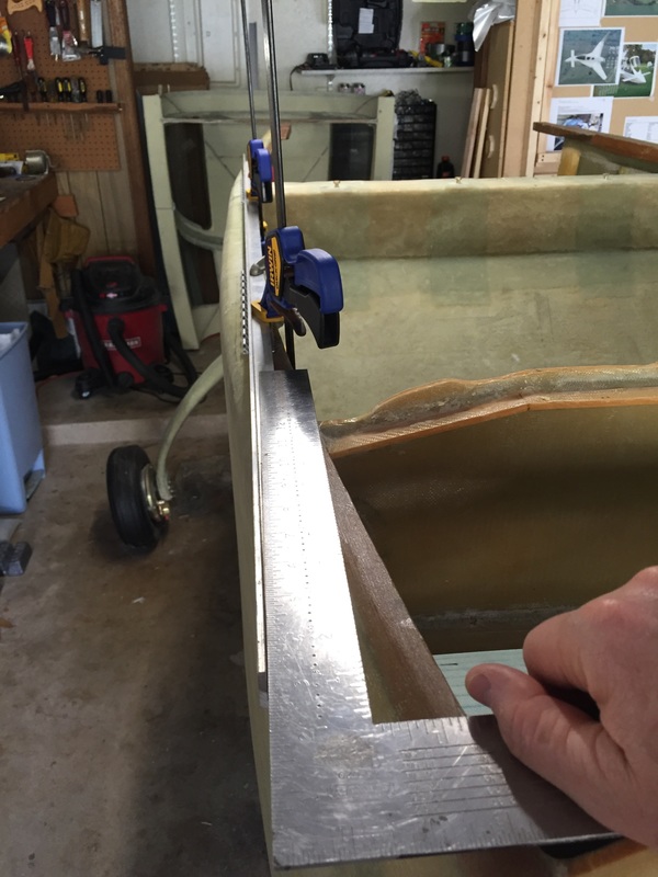
Getting the hinges aligned. If you look closely, the square is not quite "square" with the Al angle, and that's an artifact of my using one hand to hold the camera. It's the only picture I have with everything in it, so using it anyway as example of method. Floxed positions are aligned with each other and parallel with fuselage centerline.
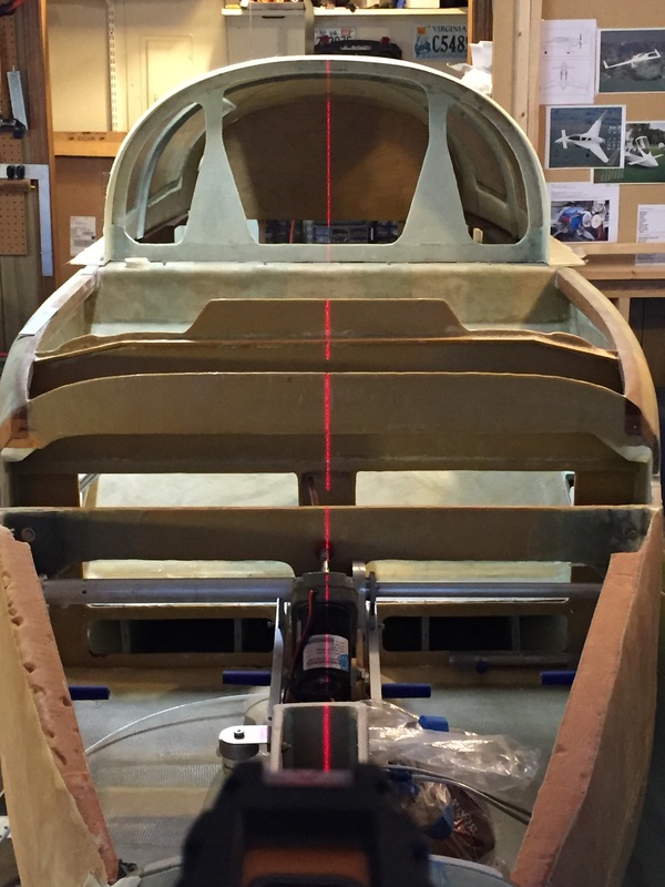
Checking and marking centerline of everything, including turtleback and firewall, again.
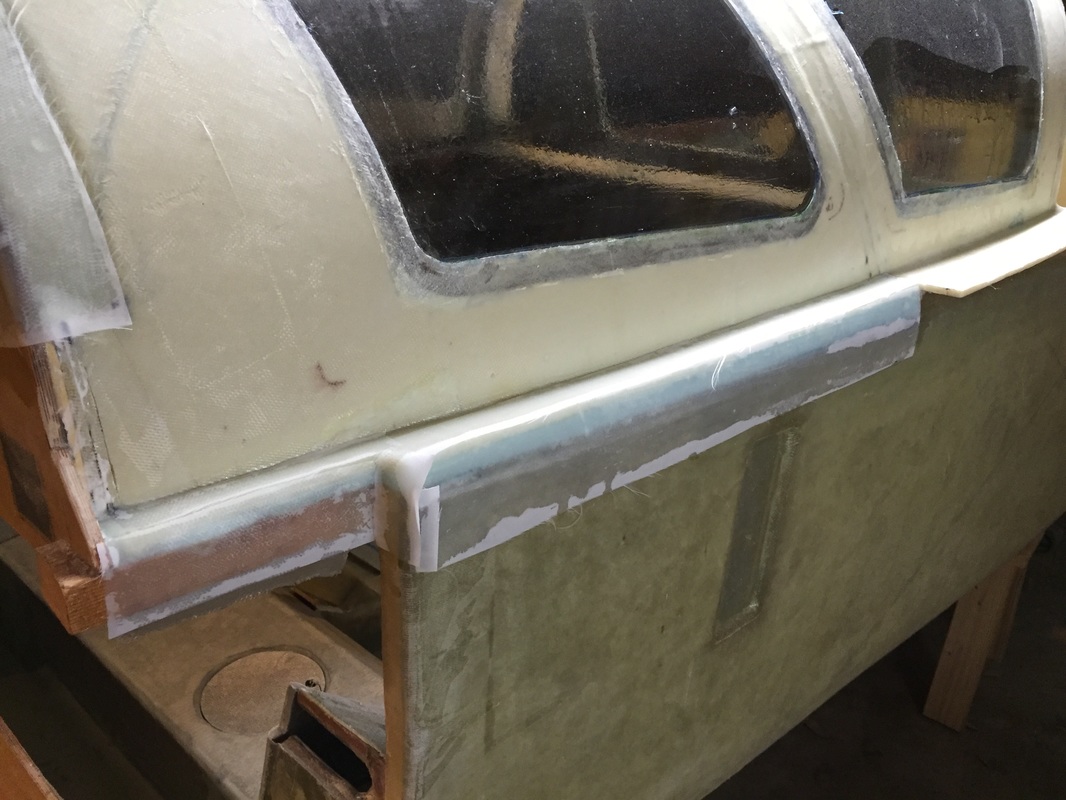
TB glassing to fuselage (aft of cut line)
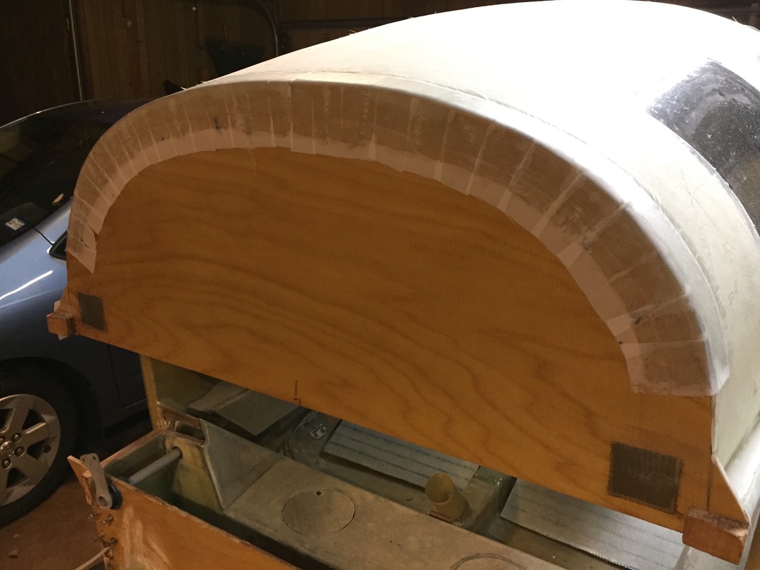
TB glassing to upper firewall.
|