Chapter 21.3 Strakes (Top Skin Final Bond through Fuel Tank Seal) |
|
This page picks up where Ch 21 Part II leaves off: The fuel system is completed to the shutoff valve from the center sump (even though these will not be glassed until I have the actual shutoff valve), and the interior of the fuel tanks has been triple checked and floxed and coated with EZ Poxy with hopefully no leaks or pin-holes. It's time to bond the top skin on, conduct pressure tests on the side tanks/sumps, then bond in the center sump and pressure check it. The remainder of Ch 21: leading edges and any loose ends with the Strakes are covered in the Part IV page after this one.
|
Final Checks before bonding Top skins to T-hats':
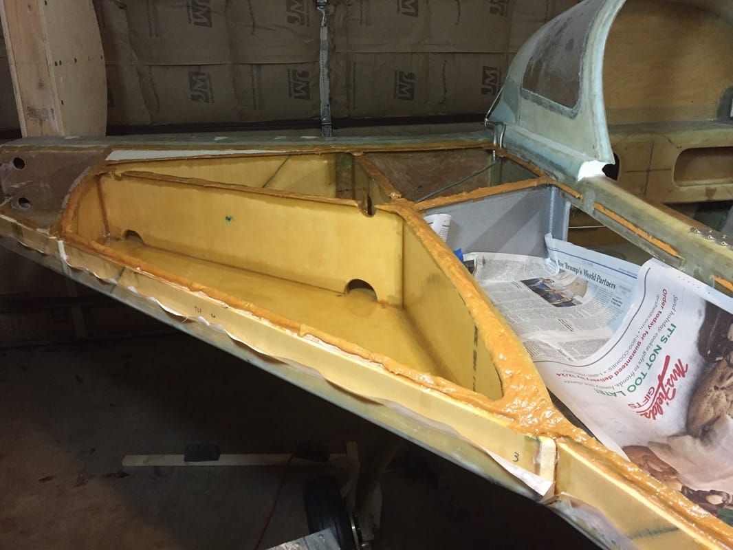
So when I thought I was ready to bond the top skins on to the T-Hats, I checked the fit again (dry fit) and arranged the weights so that they held the skin in place just like they would when the floxe was applied. This is to make sure I had enough weights and clamps ets when I actually mixed the flox up... (Each time I found some little fit thing that needed a final ajustment until the 3rd time and I was actually ready. Be prepared to postpone to the next day, if you keep finding things to fix, because once the skin is bonded on, it's extremely hard to fix stuff interior to the Strakes. Examples of things I decided to do prior to flox/bonding were: a) Apply the 2 BID tapes to finish out the baggage area to fuselage inside interface (bottom and sides only, since the top skin is not on yet) and b) Paint the baggage compartement areas (since this would be more awkward later, and it's easy with the top off). This meant I needed to decide on my interior paint plan and I went with the following (all simple rattle can implementations): - textured Rustoleum White Onyx - Rustoleum Grey Hammered Paint (has some silver in it and along with the texture, hids some of the glass imperfections) - Rustoleum Clear Gloss Enamel (to make the finish easier to clean and more wear tolerant) |
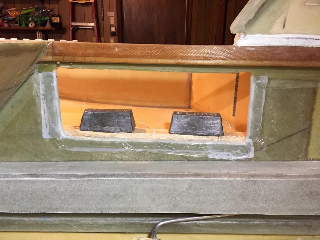
Taping the inside baggage opening bottom and sides prior to top skin bonding
|
|
Bonding the Top Skin to T-Hats:
Before you do this: I recommend completing the fuel sight gages. I didn't do this (thinking that I wanted to prove I had a good seal overall first). Later below you will see that I got a leak when drilling the holes on one side for the fuel site gages, and this would have been SO MUCH EASIER to deal with before I had the top on. But back to what I DID do: The top skin bonding turned out to be pretty simple, and the real question was, how much flox shold be mounded on top of the T-hats. I used enough to provide about 1/4" max height on a line slighly biased from the T-hat centerline towards the fuel tank side. My thinking is that I want to make sure that I have the best seal on the inside of this perimeter. See comments later on seal testing. One person helped me place the top skin on and then worked it down from the inboard/aft corner applying weights as I went. Note that I had the fuel filler cap off, to insure the tanks could breath. Placing the top skin was pretty easy since it had a notch where the fuel vent line and fuel return line came through, and once you had the notch placed around the lines, it was easy to lay it and press it without movement. I bonded the right side and let it cure 3 days before doing my light seal test (without the outter glass on the top skin yet). After initial testing of the Right side, I took lessons learned and was a little more generous on flox when bonding the left side top skin (same overall process).
|
Piling the EZ Poxy Flox on the T-hats, Note paper to prevent squeezed flox from dropping on the recently painted interior of baggage areas.
More weighting schemes for top skin (where's the kitchen sink?)
NOTE: I later added a 2nd vent line to the fuel tank on each side to enable venting when on the ramp with the nose low and tanks at least 1/2 full. This was a real pain later as I'd by then built the upper fairings for the Strake/Fuselage and had to cut them and then repair them when done. Builders: Install 2 vent lines at this stage (it's a well known improvement on the Plans vent line approach, I was just a "bone head" for not taking the time to do it at this easier stage in the build!).
|
|
Initial Leak Testing:
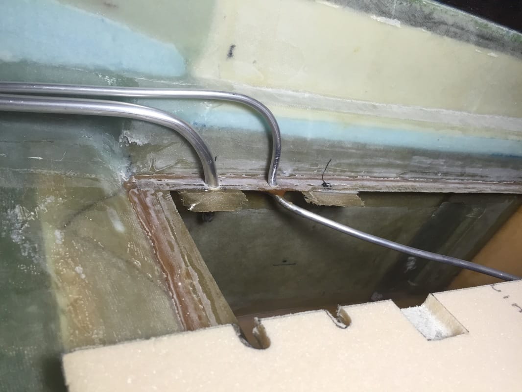
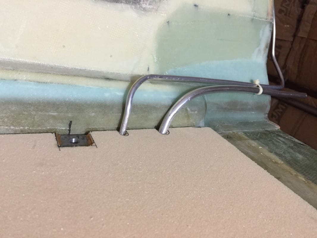
I built a simple manometer as shown in the figure to the right with a bike pump to control the pressure. Because I had a center sump arrangment I needed to seal the output from the side strakes into this sump, and the fuel return lines, which I did by making a flox ball and jamming it into and around this 3/8" Al tube and let cure. I made sure the fuel filler cap was nice and tight, and then applied 8" of water pressure (0.3 psi) through the 1/4" vent line. I didn't feel comfortable applying any more pressure than this for fear of breaking a perfectly good seal before getting the top skin outer glass on. I wanted this initial confirmation that the tanks were tight before applying this outer glass level, which might make sealing problem areas more difficult. Initial Leat Testing Results: Right Tank: slow leak (lost 8" of pressure over 4 hrs). I searched with the soapy water method and found leak in the 3/8" outflow Al tubing that I'd tried to cap, so I re-capped it. I need to get very meticulous to find the remaining small leak. I did a little flox filling around periphery (stake/spar seam top, strake/fuselage seam top, R57 top seam outboard) and still not completely sealed. I'm ordering a USB borescope that's 2 meters long to use for investigating the tank seams from inside. Remember that I've already got access through the fuel filler port. I'll come back to this paragraph when the scope comes in and I have a chance to work with it. Left Tank: had a leak in the leading edge corner of the Left Sump near the fuselage (lost 8" of pressure in 1 minute) but this was easy to find and with a slight vacuum on the tank I used a syringe and EZ Poxy to fill the hole and glassed over it with 1BID. Tested again over 5 days with no loss of pressure. Smoothed the outer foam and glassed it per plans to protect the foam from damage and allow for higher pressure testing. Pressure test (varying with Temperature - maximum of 18.5" H2O pressure) over 10 days shows NO LEAKS LEFT TANK (WOO HOOO!!!!). Updated Leak Testing on Right Tank: I used a variety of methods for leak detection on the right tank and was very slow and deliberate. I was particularly troubled by not finding anything in several tries with the bubble film method. I looked around all the fittings and all the seams and just couldn't find anything. I knew it was a very slow leak from watching the manometer and the one place I could not see was the hole I'd patched in the spar that WAS the access hole for the inboard wing bolt. So I got an AC coolant pressure fixing bottle from Pep Boys and ordered a freon sniffer from Amazon so I could try this method everywhere (including deep in the spar, accessing from the back seat. Low and behold the first time with this setup I got a very repeatable signal from that little hole patch I'd done. I should have been more careful laying that 4 BID patch. The fix was standard practice, but a real contortion: gloved finger of super wet EZ Poxy flox (just so it would stay on my finger long enough to reach my hole arm down the spar) spread all around this hole where the patch overlays. I then pulled a slight vacuum on the tank to pull the epoxy into any leak hole. Then I went back and with finger again put a little more normal wet flox in the hole area, and left to cure. 2 Days later, I pressure tested for 4 days: NO LEAKS RIGHT TANK (WOO HOOO!!!!). What a relief! Time to glass the top outer skin... |
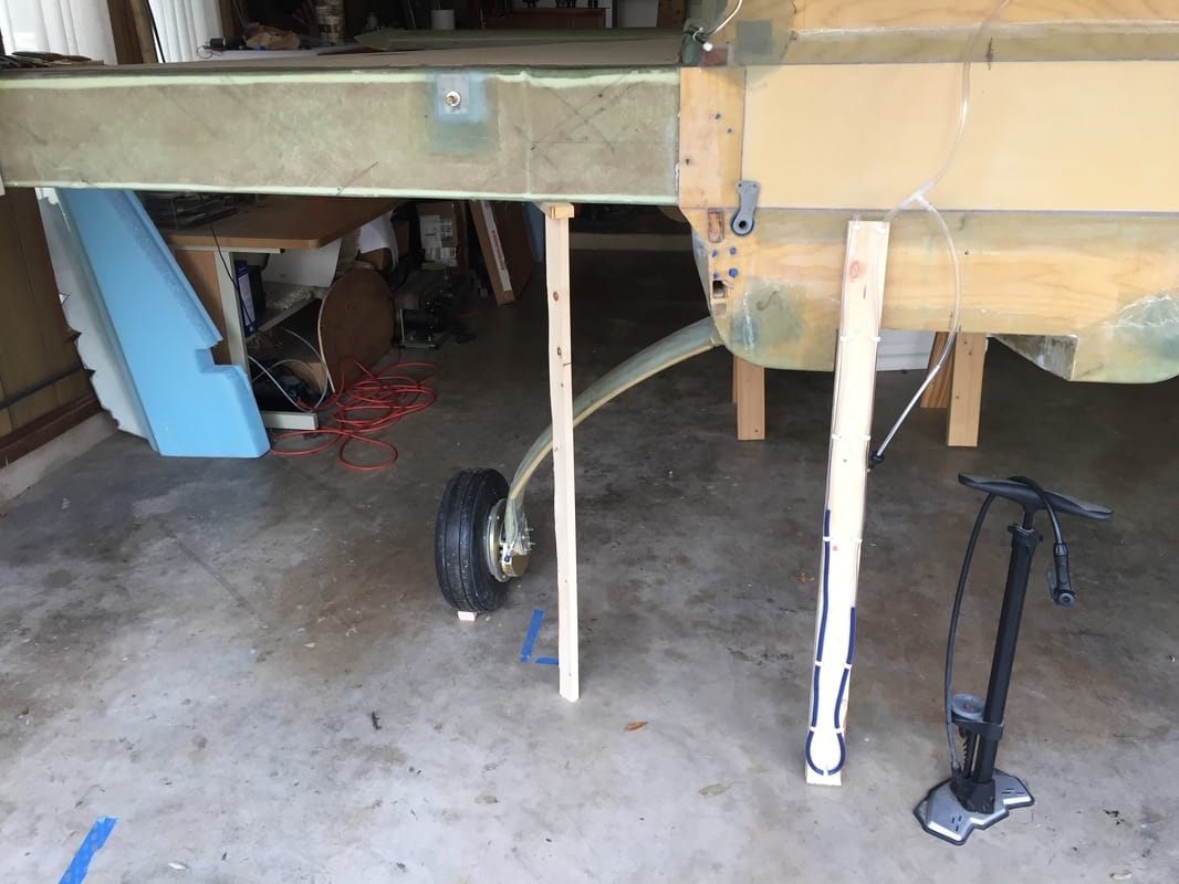
Manometer for leak testing. 1/4 tube from top of T fitting goes to vent tube.
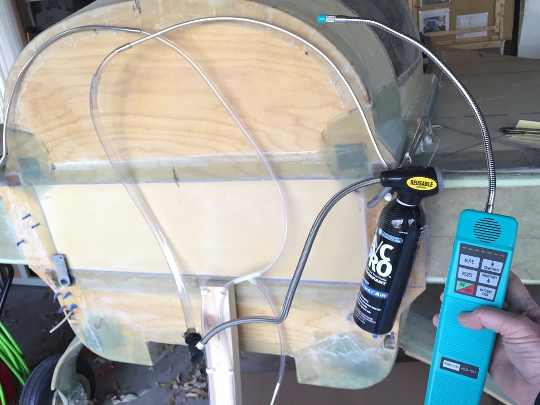
Auto AC booster connected to the vent line (of the R tank). I'm holding the halogen detector I used to find the leak in the spar access hole patch I made for the inboard wing bolt).
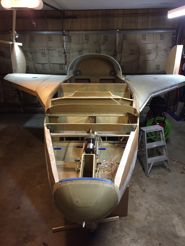
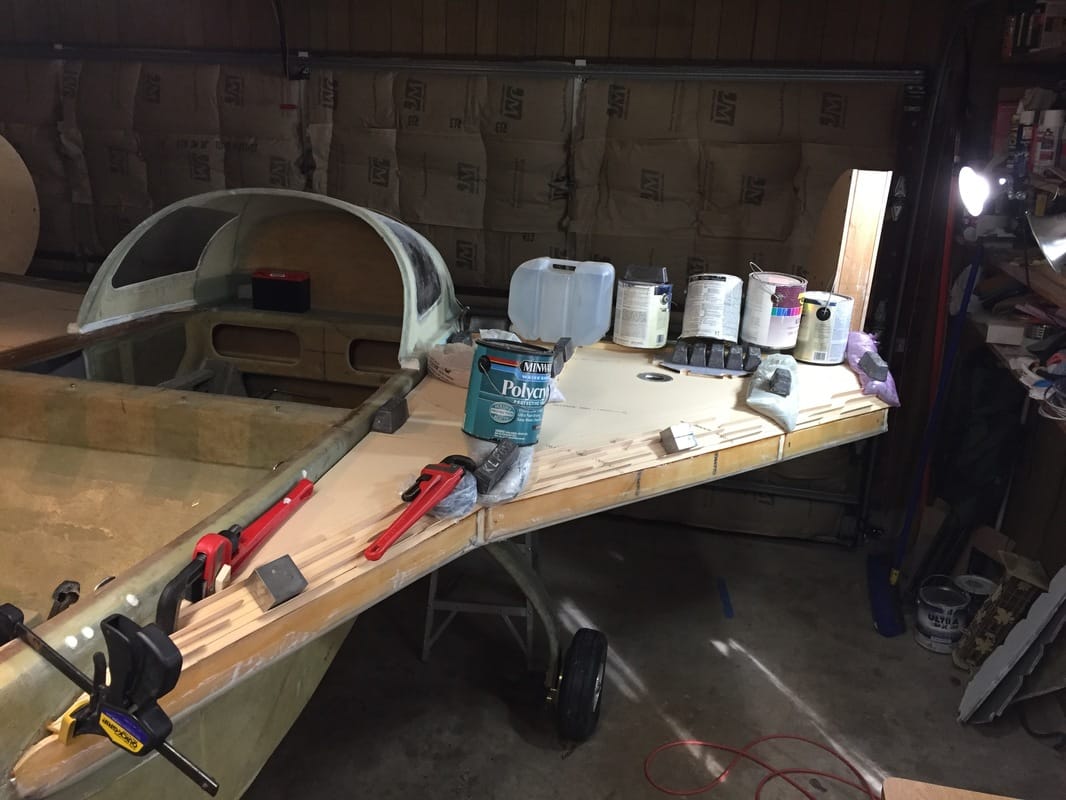
Both top skins bonded, and L tank seal test passed, so it's got outer skin on. The R side outer skin was completed too after this tank passed it's leak test
|
Fuel Cap Finishing:
Before final pressure testing I needed to glass the outside of top skin to complete the sandwich structure for pressures above about 5-6 inches of H2O. When I did this outer top skin layup, I masked the fuel cap and once cured, used a Dremel to carefully trim the UNI down to the edge of the masking tape to remove the little piece over the cap as shown below.
Before final pressure testing I needed to glass the outside of top skin to complete the sandwich structure for pressures above about 5-6 inches of H2O. When I did this outer top skin layup, I masked the fuel cap and once cured, used a Dremel to carefully trim the UNI down to the edge of the masking tape to remove the little piece over the cap as shown below.
Masked fuel cap before outer top skin layup.
|
Dremel trimmed outer skin around fuel cap after top skin layup
|
|
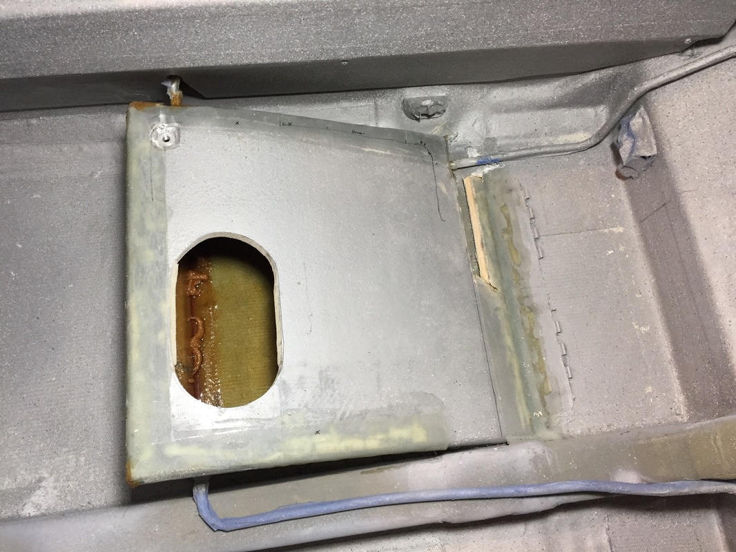
Fuel Site Gages Installation
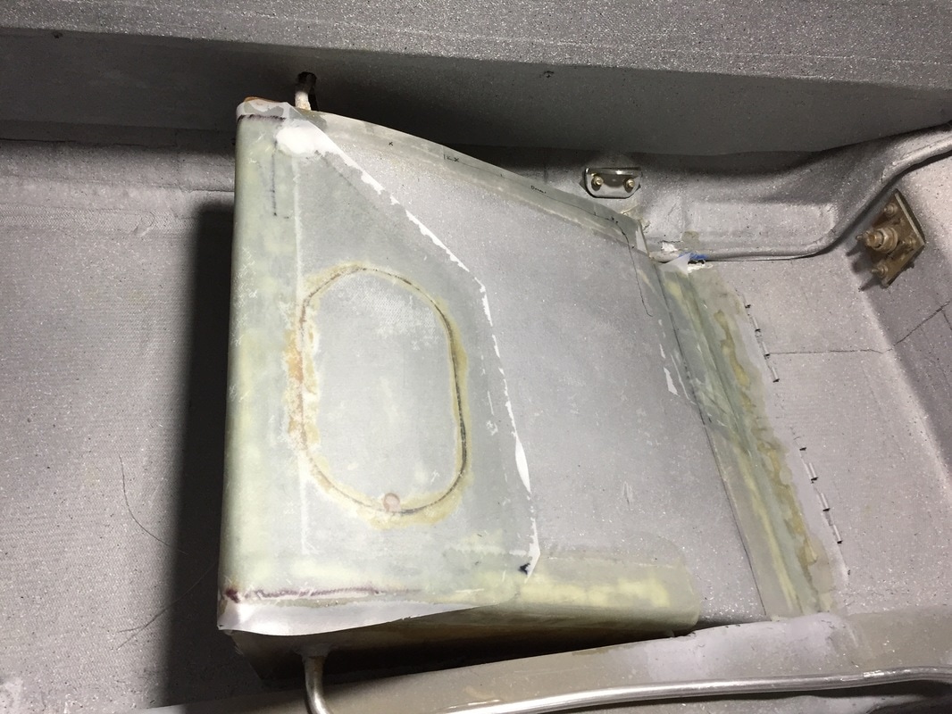
As mentioned in previous section, I wish I'd done the fuel sight gage installation before I'd bonded on the top skin of the strakes. The install involves floxing an HDPE plastic backing plate and then drilling through this plate, and the fuselage in a region where the outside skin is bonded to the inside skin. See figure to the right. When you do this, of coarse you created a perforation in the fuel tank area and my initial logic was that I should do this after I've proven that I don't have a leak elsewhere since the likelihood of leaking here is extremely low (no foam sandwich). But I did get a leak in the Left tank when I did this, and I didn't know it until I could test the tank after "sealing" the holes by covering them both by floxing on the clear bubble window. Note that my Right fuel tank sealed up just fine, as it should have, and I tested it for a week to confirm. I focused on the Left tank with the Halogen detector again: every seam and fitting just like I'd done before doing the sight window and everything still looked good. I also got no readings around the periphery where I'd floxed the plastic sight window pieces. So I assessed from looking at other's experience, that somehow air was leaking between the inner and outer fuselage skin (even though there shouldn't be a path there) and then getting to the atmosphere somewhere far from the sight gage that I couldn't find. This suggested that I needed to have a way of sealing up the drilled holes for the sight gage. I'm still in the process of performing this seal, and testing, but here's the approach I'm taking: - use an endoscope to look from inside the tank and make sure that I didn't accidentally perforate the top or bottom inside skin when I drilled the sight gage holes (actually did this during my leak hunt). This is not easy as you need to snake the endoscope (mine is a 2 M long 8 mm diameter WiFi enabled device) from the fuel filler cap area through one of the half circle slosh openings in B33 so you can see the fuselage where the holes go through. My holes were a good 1/4" from the floor and roof of the fuel tank and no nicks could be seen (Good). - drill through the clear window and the previous holes to open them up to 1/4" diameter (I know this messes up the clear window at it's top and bottom). - I then mixed EZ Poxy flox (fuel resistant) and cut the tip off of a 1/4" insulin syringe ( cheap packages of them from local drug store) and used this to push flox into the new larger holes. - I'm currently waiting for this flox to cure really hard (doing other things) and will run a pressure test. Assuming the test is passed, I know I've plugged the leak with the flox and I can drill a new 1/8" hole through the center of this flox to expose the clear window again. This will unseal the tank but I know that the seal is now needed in the clear window, which I have direct access to. My plan is to glass over these 1/4" holes and hopefully I'll be done and have a fully sealed L fuel tank... Finished the L fuel site gage fix: I started the description of this above and returning to finish out this page. After the L tank passed the pressure test (8+ inches of water over 4 days without loss) I glassed over both holes I'd made in the clear bubble window as shown below, and again tested for 4 days with no problems. I Finally have both strake tanks completely sealed! Now I'll open the drain lines to the central sump (which have been plugged with flox) seal the lid on the central sump, and plug the outlet fuel line from this sump and test all 3 tanks together. See next section below 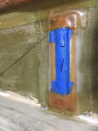
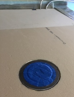
Final glassing over top and bottom of L fuel site window bubble
|
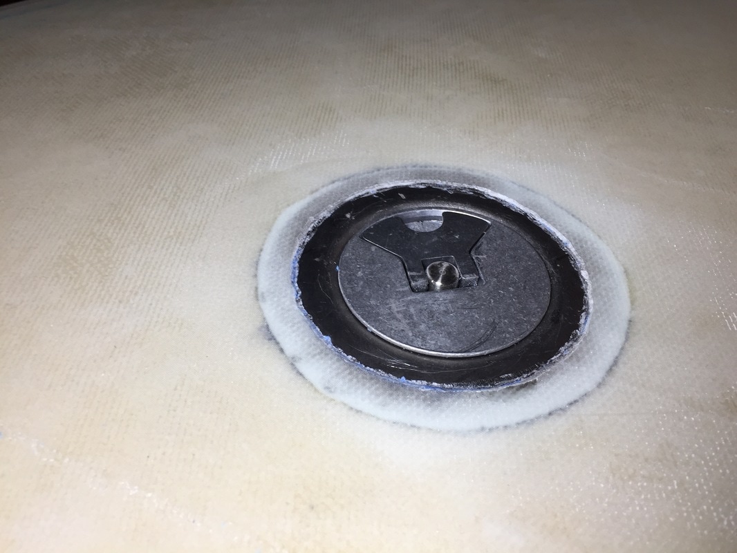
Fuel sight gage installed and clear window masking partially removed to show the 1/8" hole to the tank
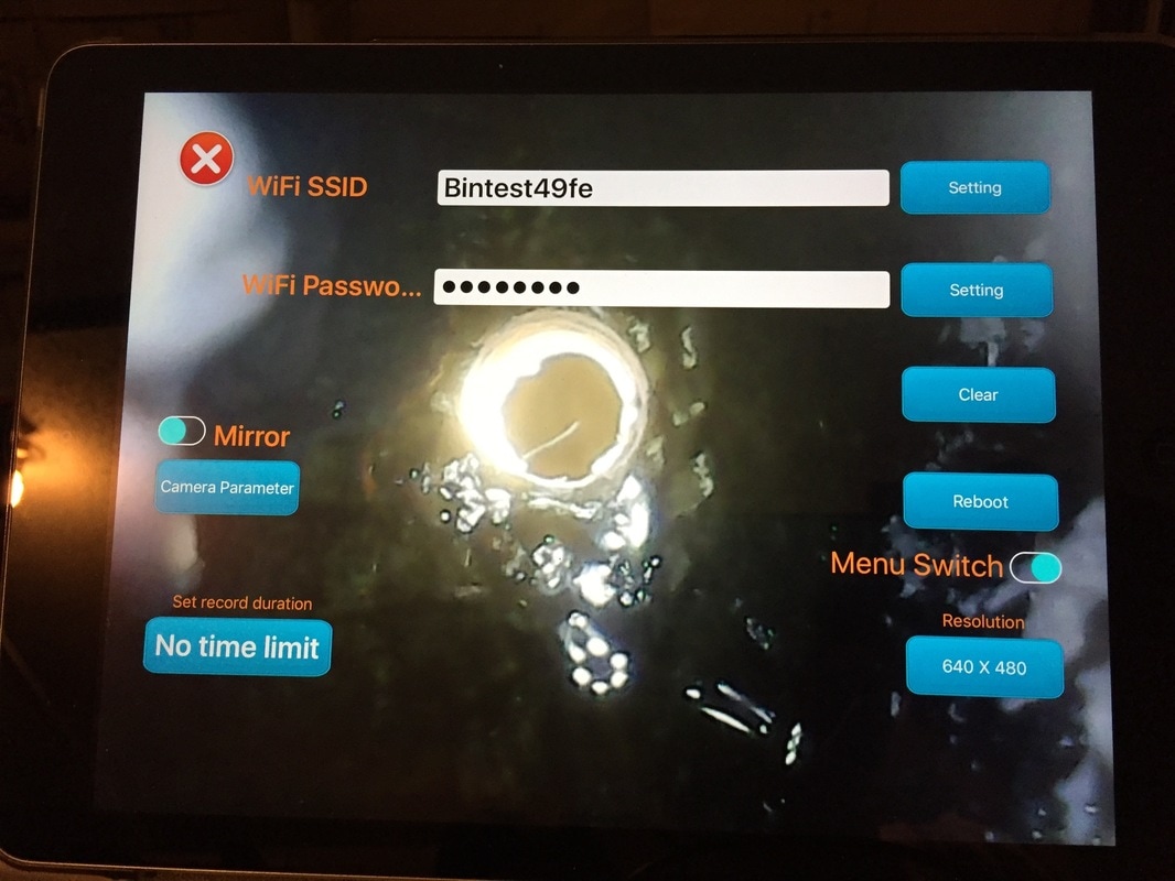
Endoscope view of hole after opening up to 1/4". I use this view to know how much flox to push through the hole later (enough to fully fill hole and start to sag, but not drip)
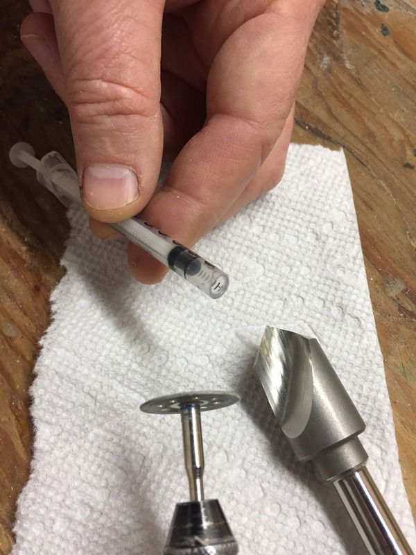
Modified insulin syringe
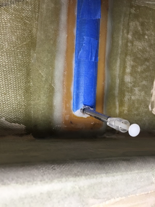
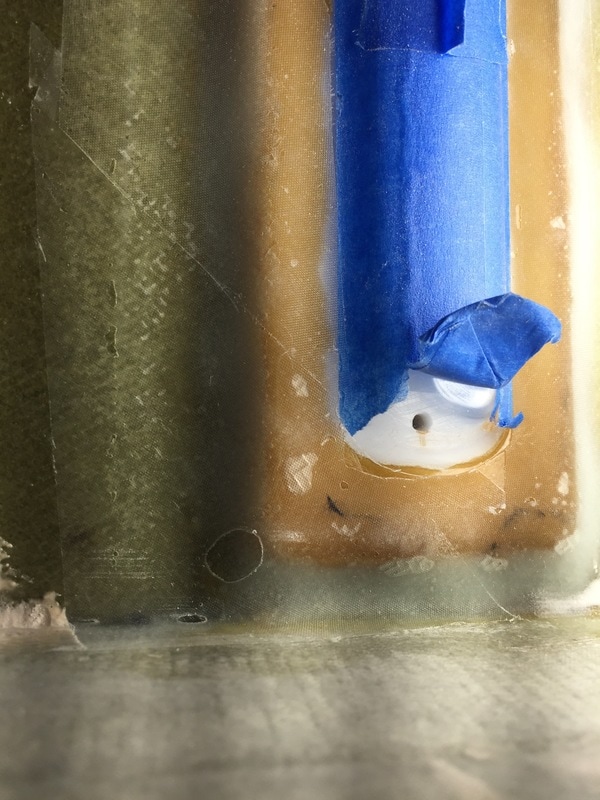
Syringe positioned to fill hole with flox without filling the window with flox...
|
|
Sealing the Center Sump
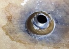
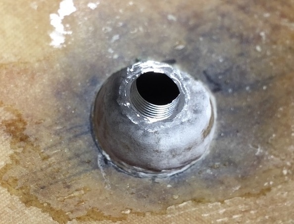
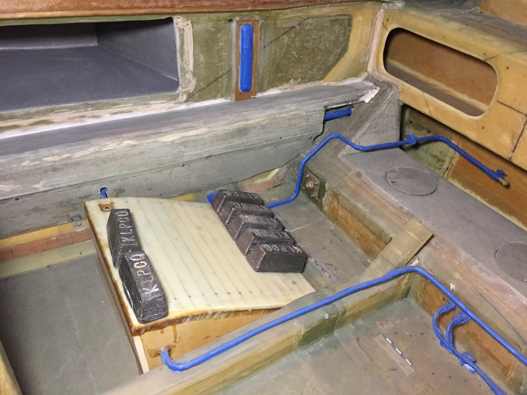
This picks up where I left off with the center sump construction that had to wait until I had the strake tanks sealed. Previous work on the center sump can be found near the bottom of Strakes Part II. At this point, the sides of the sump (which is also the right rear thigh support) had been built and bonded to the floor of the rear cockpit and the inlet and outlet fuel lines run as shown in the previous work description. I'd built the lid, but had not yet inserted the hard point for either venting or sealing with a "burp" plug in it's high point, so that was the first thing to do. The hard point was cut from 6061 1/4" Aluminum plate and drilled/tapped for 1/16" NPT fittings. Daniel ??? from UT Austin scrounged the brass 1/16" plug and tubing fittings shown in the figure to the right from his stash at home, which was much appreciated, as these fitting sizes are a little harder to find than 1/8" NPT. Note that my plan is to use the plug shown in the hard point, just as Vance does, but I have a backup option with the extra fittings, to run a 1/16" vent tube line up the the vent manifold on the top aft face of the firewall later if necessary. I built up a flox bead on the flanges, just as for the strake top skins and weighted the lid down to cure. A few days later, I tested the whole system of tanks (strake tanks already both fully sealed and passed tests prior to this point) and there was a significant leak. Bummer! I eventually fixed this but want to note a few mistakes I made in the above process that would have made this MUCH more likely to seal on the first try: a) When I bonded the sides to the floor, I had to use a lot of weight because the floor surface was not completely flat (like the table was that I built the sump sides on). The non-flat surface was due to the 7 ply seat belt hard point layup shown in Figure 17 of Ch 8. An option here would have been to trim the bottom of the sump sides so that they fit the layup contour. Not trivial, but could have been done. b) The next thing I could have done better was not to have glassed the outer skin of the lid until it was bonded (with the hard point sealed in) to the sides of the center sump. This would have more directly mimicked the process used for the strake top skins. c) Given that I didn't do either of the above, I could have used more weight when bonding the lid down. I didn't do this because I was worried about leaving a high residual stress in the lid when the weights were removed. My concern was that this residual stress would cause a delimitation or crack in the flox before I could get reinforcing layups on all the outside edges. This was probably not an issue, and I had to do a repair anyway. It might have been worth the risk? d) I could have used more flox... yea. OK, after beating myself up for this I realized that I needed to move on, find the leak, and fix it. By listening I could hear air coming out somewhere near outboard aft corner, so I cut the overhanging lip in that area to get a better view. I then realized that the leak could be anywhere on the outboard side and possibly being conveyed to the corner since I had already 2BID'd the lid down on all sides. At this point, I began to realize that the only way to really know I was sealing this sump, was to do it from the inside. So I made a plan to cut an access hole in the top of the sump, check and re-seal the whole inside lid edge, and then patch up the hole. This was a big decision and I thought it through carefully. the hole needed to be big enough for me to get my arm inside and reach every corner and edge. It also needed to be a shape that was easy to repair, and also not so big as to interfere with the reinforcing rib I'd built into the inside of the lid (see Strakes II for picture showing the inside of the lid with this rib). I did in fact do all this and I'm documenting the access hole creation and repair in the Special Cases Page of the Tips Section of this site. The other key thing I did was use my endoscope (also critical when I was sealing up the L strake tank near the fuel site gage described further up on this page) to inspect and localize where the most likely leak areas were from the inside. I used a little flox around the whole inner seam, but I knew where I really needed it. Remember the flox work was blind and applied by feel with left hand, first finger... Once the repair was done I re-tested and had only a very slow leak. I checked everything with the halogen squirt bottle/tank pressurization/halogen detector used in the strake tanks, and quickly found that the culprit was the floor plug to the central sump which was not screwing in tight due to interference from flox left when this hard point was emplaced. Pictures to the right show before and after I cleaned this up. Reinstalled plug and pressure test is ongoing now (3/27/17) but it looks like no pressure loss after a couple of days. Postscript: Tested all tanks for 3 weeks with no sign of leakage. Moving on to canard finishing... |
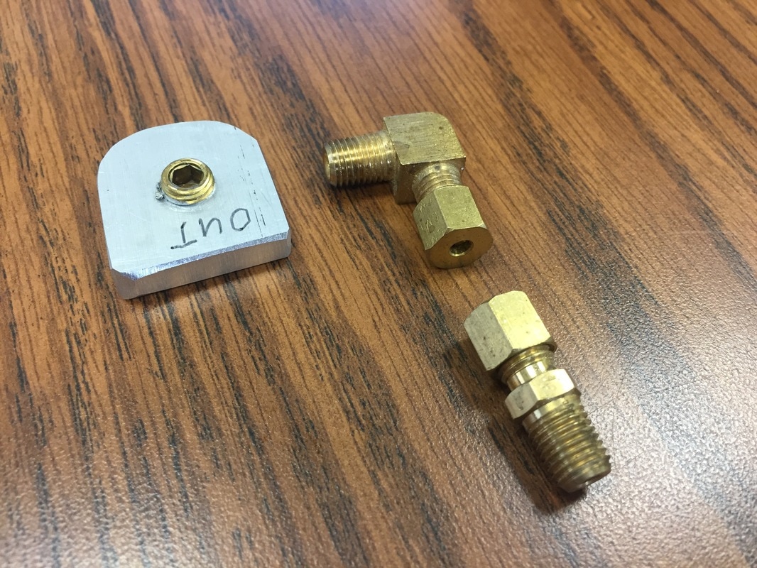
Vent/Burp plug and hard point for Center Sump Lid. And extra fittings if I choose later to run a vent line to the vent manifold on the firewall.
Bonding the lid on the center sump
Repair complete, access hole sealed, and glassed over.
|