Chapters 10-12 - Canard and Elevators and Installation in the Fuselage |
|
I bought a partially completed canard and partially completed elevators from David Pierce, and in this section I will go over the fixes and remaining work required to complete Ch 10-11. The canard had not been fitted to the fuselage, so all of Ch 12 was done by me and described below.
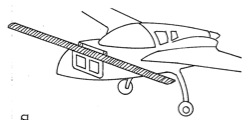
Left canard tip after sanding back the glass and foam to match the proper curvature of the Right tip
Micro, Glass and Peelply on updated shape. You can see the clay profile curves on the table that I used to match the other canard tip
|
Ch 10 Canard (Completion/Fixes)
The main thing I needed to do to the canard was get both tips to the proper shape. One side had the appropriate smooth upward curvature but the other was blocky. Thankfully it was a material removal task rather than a material add task. I used clay to make some templates of the good side and then used them on the blocky side to judge how much foam to remove so that both sides would match. This also gave me a chance to improve the flox corners on the sharp tips on both sides as well. |
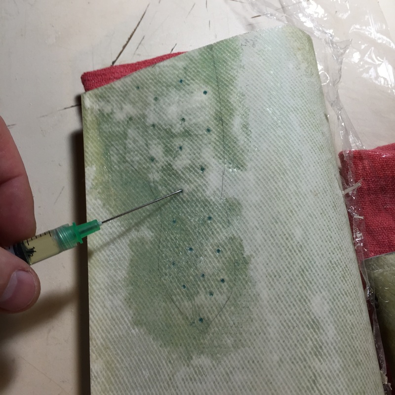
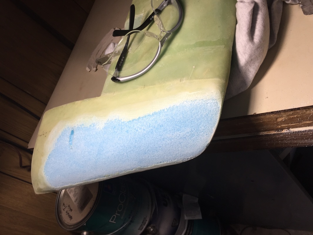
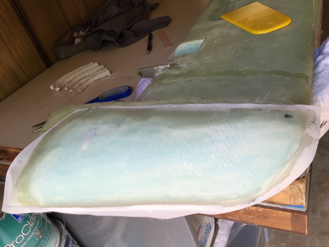
injecting epoxy under concave elevator skin
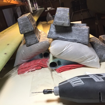
Weighting skin for cure with sand bags (note use of plastic newspaper delivery bags to prevent sticking)
|
Ch 11 Elevators (Completion/Fixes)
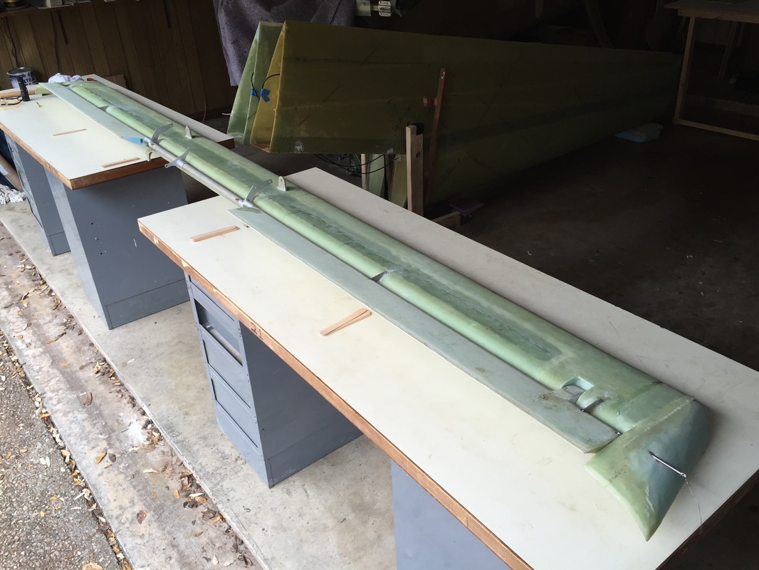
David had done a very good job keeping the elevators light in their layup. I found a few spots, particularly close the the inboard and outboard edges, however that because of conservative use of epoxy, the bond with the foam had been lost. This was aggravated when I was trimming the inboard edge to match the fuselage profile in Chapter 12, and this work was actually done after that step, when I realized the size of these regions. To repair this I first marked the estimated area of de-bond with a pencil. Then I used a 1/16" drill to make a few holes in the layup and a syringe to inject a small amount of epoxy under the layup to create a new bond with the micro'd foam. The picture on the left is the 1st one I did and I could have done this with 1/2 the number of holes. It was easy to see the capillary influence on epoxy spreading under the layup, which was good, as it insured good penetration to all areas that didn't have a good bond (see darker green areas in photo). I used sand bags to weight the plies against the foam during cure. I also needed to do an alignment check with the elevators assembled with their connecting torque tube to insure that the trailing edges formed a continuous line. I did this by setting up the elevators across 2 of my 6 ft tables and bolted on the torque tube. I carefully leveled the tables with each other, and then checked to insure the trailing edges were true by looking down the edge line from both ends, as described on page 11-6 of the plans. Trailing edges and bottom flat portions of the elevators were completely aligned and flat respectively. 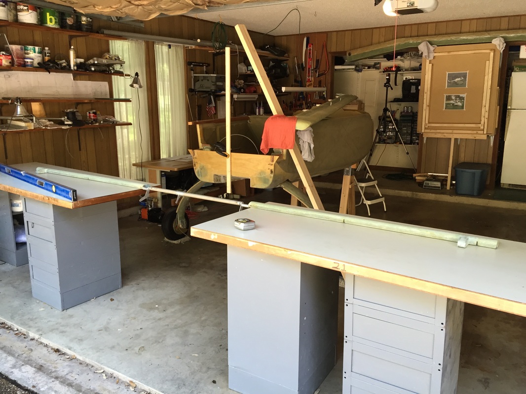
Leveled table for alignment check of elevators with connecting torque tube
|
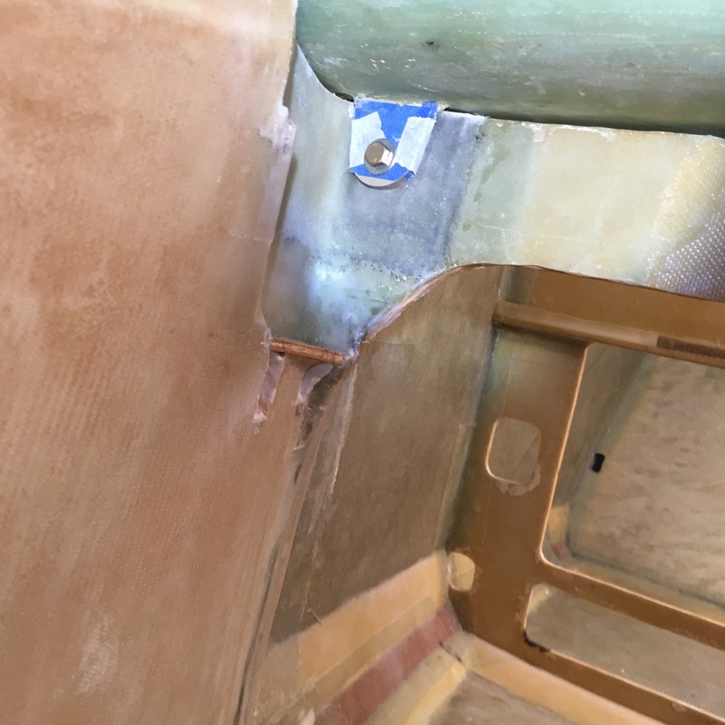
Right side canard main support in F-22. 1/4" buildup on this side extended 3 plies forward onto the nose sides to make strong corner shown in Ch 13.
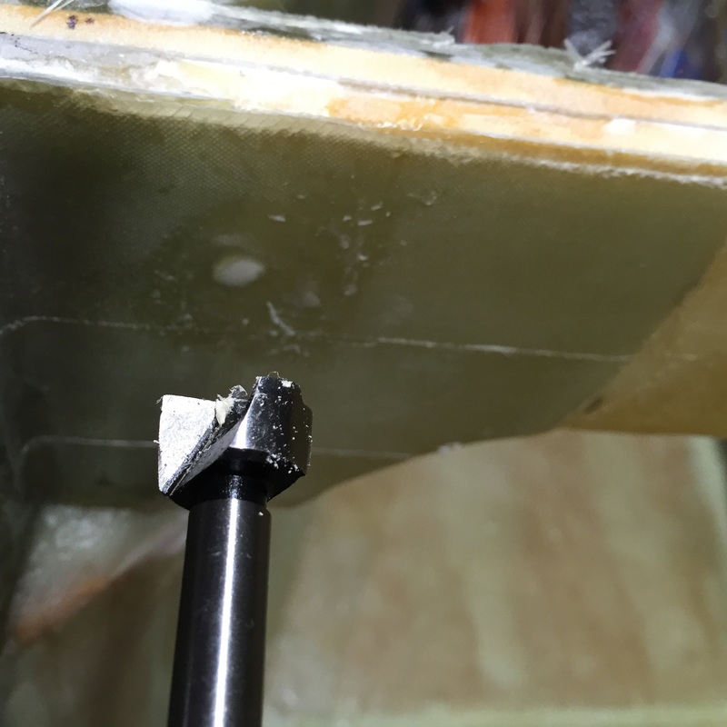
Flox fill to allow Forster bit to get start in center of 1/4" through hole.
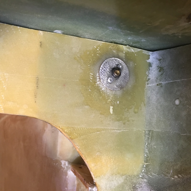
1/4" Anchor Nut riveted to washer and glassed to back of F-22 during curing of main bushings with 1/4" bolt holding everything in alignment.
Upper Tabs installed
|
Ch 12 Canard Installation in Fuselage
Canard installation was complicated by the fact that sides of the nose (Ch 13) had been started and they prevent direct access for a drill to make the support holes in F-22. Here's how I dealt with this: (I wish I'd taken more pictures - to go with the extensive text in my build log...) Step 0: I needed to create room to work just forward of F-22 so I cut the inside skin of the nose sides, and removed the foam to the outside skin in the region of the canard tab attachment. You can see this in the photo to the left where the job is finished. Step 1: Align the canard by first getting it's centerline positioned coincident with the fuselage centerline with a laser and leveling it's top with the longerons. I also made the incidence blocks F and E and used them to shim the canard incidence. After this I used incidence block G for canard and elevator alignment. I then measured from the outboard corners of the aileron cavity to the fuselage centerline as shown in Figure 5 of Ch 12. From this I found that I needed 0.25" of thickness on F-22 on the Right attachment point so I applied a 19 ply BID patch as shown in the figure to the left to F-22. the last 3 plies of this patch also extended 2" around and forward on the inside of the nose outboard skin that was exposed after I removed foam for clearance. 3 plies were also used on the Left side to create the solid corner structure as prescribed in the plans Ch 13, page 7, Fig 34. Step 2: I needed the holes to align with the support tabs that are built into the bottom of the canard. As per plans I needed to make the initial through holes from the forward side. Since I could not get the drill into this area, I used my dremel with a right-angle attachment to make this #10 pilot hole from the front (using the canard support tab #10 holes as the guide). Leaving the canard clamped in place, I then drilled the 1/4" hole from the back side of F-22 using the #10 hole as a guide all the way through the canard lift tabs. Now I had good aligned bolt hole for the canard support, and used the AN 3 bolt and nut to hold everything together rather than clamps. Step 3: I then moved to the upper canard tab area: Rather than make these tabs from .2" clark foam I made them from the .25" very dense aviation plywood used for the firewall. David used this same much stronger stuff to make the longer NG-30s for this Cozy. I made the round nosed alignment pin by cutting off the head and drilled and floxed it into the longerons forward of F-28 per plans. I then followed the plans (Figs 8-14) glassing these tabs in place on the canard and installing the appropriate bushing for easy removal. Some have described difficulty removing the canard, but even though it's a tight fit in installation, I don't have a problem removing it by inching it forward until free of these pins. Step 4: With the canard well aligned and mounted now at 4 points I removed one of the AN 3 bolts and drilled it's hole out to 1/4" and used the AN 4 bolt. Then same for the other bolt. Step 5: Now it was time to get the bushings into F-22. I could not get any of the tools recommended into this area from the front of course, so removed the canard and used a 5/8" Forster bit to open the hole from the rear. To get a good start on this I re-filled the back of the hole in F-28 with a little flox to allow the point of the forester bit to get an initial guide line going. Once about .2" in, the point could follow the 1/4" hole. This is not easy, and if you have the 5/8" boring tool from the landing gear attachment to bulkhead (which I didn't have) just use it with the 1/4" guide rod. My method worked fine, but was more risky on getting a good straight hole. Step 6: I riveted the 1/4-28 anchor nuts to the washers and ground the main bushing lengths down to just less the hole lengths of the F-22 5/8" holes I'd made. While floxing in these bushings, I also glassed in anchor nuts to the back of F-22 so the whole canard/bushing system could be bolted for curing. Note that you need to wax the bolts and re-measure to confirm good canard alignment for this last step (should be good if you've been careful following the plans). The order is important to retain alignment you established at the beginning of the attachment process. |
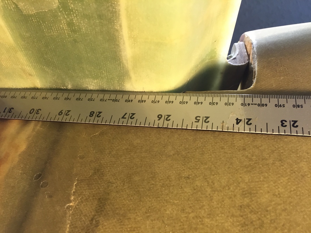
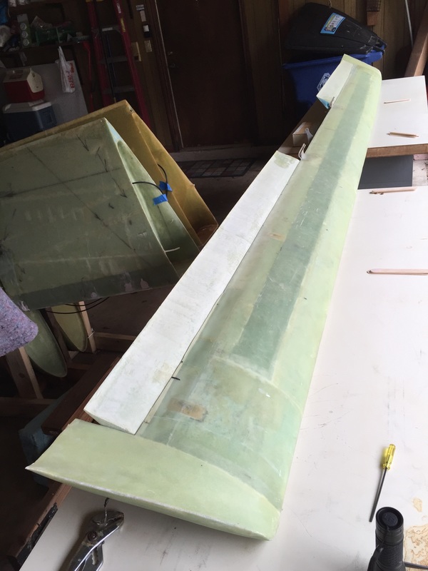
Using thickness of ruler to get the offset line marked on under side of canard
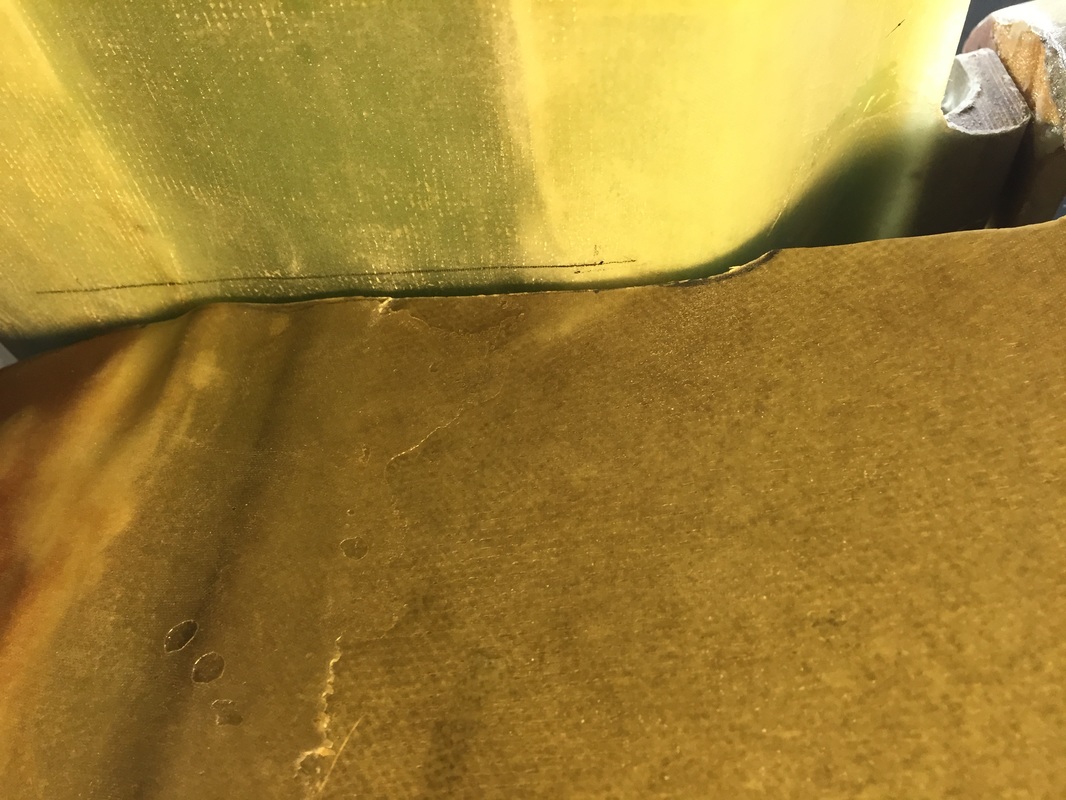
Pencil line on canard for trim of elevator (elevator marked when mounted on bench to canard)
|
Ch 12 Elevator Edge Trim to Fuselage:
Once the canard was mounted to fuselage, the elevators could be trimmed to provide the prescribed gap with the fuselage sides. This is a little tricky because you can't set the canard/elevator combination in with an interference. I solved this by marking the under side of the canard with it mounted on the fuselage without the elevator with a line running parallel to the fuselage but offset by .08 thickness of the ruler (see picture). I then removed the canard, put the elevator in place and extended this line onto the elevator to see where it needed to be trimmed. Once installed with the trimmed elevator (pivot pin through elevator but not through torque tube yet - see below) I could do any fine trimming, since the fuselage-elevator gap gets smaller as the elevator is angled down and bigger as it's angled up. I've seen some flying examples (pictures) were the builder put a fillet on the fuselage to control this gap better, and I may do this too, eventually. 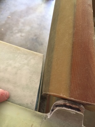
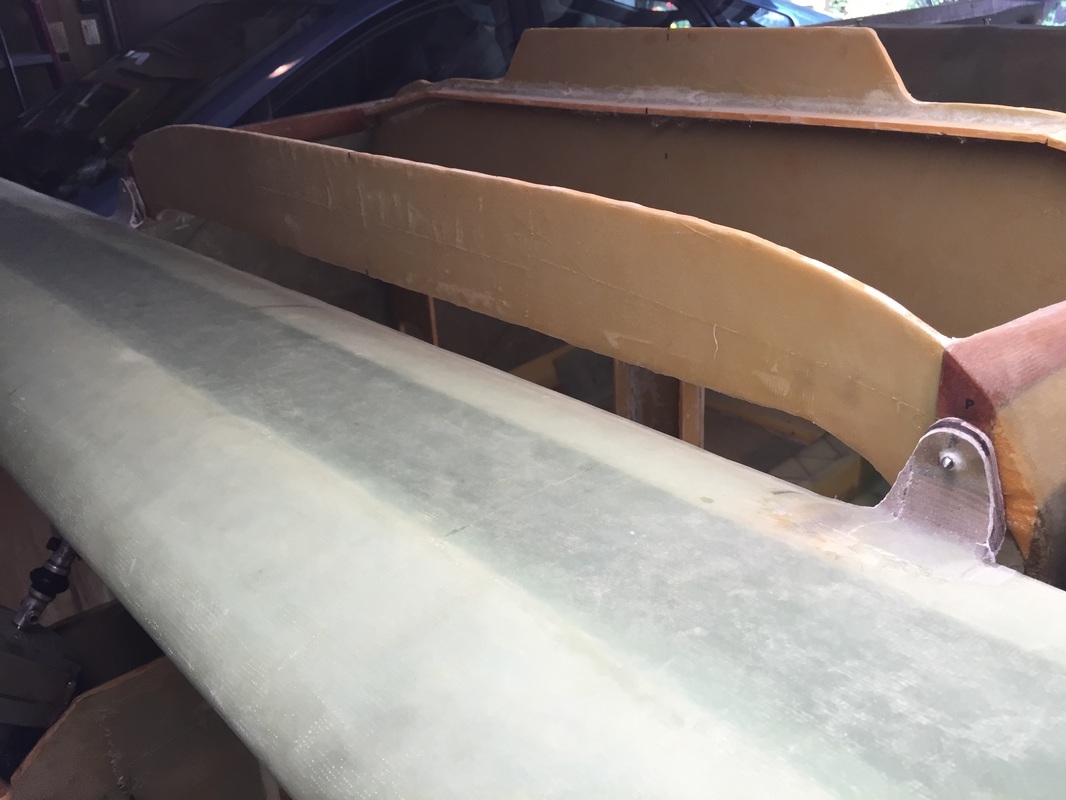
View of gap variation when elevator is in full "up" position. It's even 1/8" in zero angle position.
|
Canard upside down with successful pivot pin insertion (see stir sticks after I pulled them once the rod was through each support tab)
Canard flipped right side up (with support) so I could get the pin through the inboard most holes.
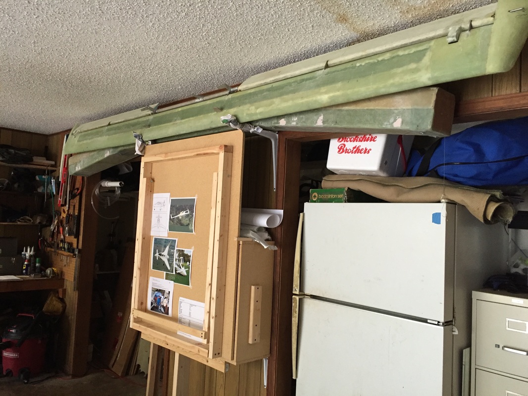
Canard stored safely with elevators fitted, waiting for Controls installation
|
Elevator Insertion in Canard with Torque Tube:
With the Canard essentially done, and the elevators shaped to fit the fuselage I was ready to put them all together and store them until time to mount and fit the elevator controls and trim (see Ch 14-15). I had tried to do this once a few months back when I was working on the canard and elevator (timeline of above), but had not been successful in getting the elevator pivot pins all the way through. I HAD been successful on one previous occasion getting the elevators mounted without the torque tube, but wanted to be sure that the whole thing would go together, now before storing it. This is a tricky operation because the stainless steel pivot rod is running hidden inside the elevator and threading through several holes that are tight fits. It takes lots of patience and here are a couple of tips that helped me be successful. Other builders may have other hints as well: a) Make sure the SS pin is straight. If there are any bends (no matter how slight) you may be at great disadvantage. You can check this by rolling the pins on a very flat surface and looking for uneven rolling. The pins are so long and flexible enough that you may not see this by looking down the pin like you can for a board. b) Make sure you have the outboard end prepared as plans indicate with a little wire extension through the hole. Removal is much easier with this once you have inserted the pin all the way. c) help support the elevator so that it's holes are closely aligned with the holes in the support flanges. I used wood stir sticks wedged between the elevator and the canard trailing edge, with the canard upside down for this. It doesn't have to be perfect, but close helps (particularly if you are working by yourself). d) Put a very small amount of light oil on the rod (I used WD-40 because it's very thin and evaporates later). There is very little friction in the rotation direction, but there can be substantial axial friction during insertion, and just a tiny amount of lubricant is very helpful. e) Try first with the insertion end tapered as drawn in the plans. If you are having trouble "finding" the hole part way through the elevator, the first thing to try is turning the canard right side up. Note that you will need something to prop the canard in this position to keep the 2 canard support tabs and the torque tube weight levers from touching the table and rocking the canard. f) If you continue to have trouble getting the tip of the rod to "find" the holes going in, and turning the canard over doesn't help, pull the pin, and reshape the tip so that the point is biased to one side. Now when you rotate it, the point will "search" a wider area. This was all I needed in the final install to be successful (though I still had to flip the canard on one side. Motion of the elevators with the pin fully installed should be very friction free. In my build, this was time to store the system securely on the wall for later time to mount controls. |