Chapter 20.2: Attaching Winglets to Wings
|
|
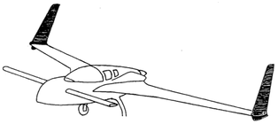
I returned to Ch 20 to attach the winglets after finishing and priming the fuselage with strakes and canopy. I waited as long as I could for this because storing the wings and winglets separately can be done very efficiently (see end of wings pages). Here we pick up on Step 3 of Ch 20.
|
Initial Jigging and Attachment:
I followed the plans and trimmed the upper winglet with the template from M-20 then with the wing sitting on padding on my table (note that it doesn't have to be waterline leveled) I used the plans method to position and jig the winglet as prescribed. I did need help from my wife holding the winglet in place while I used a single 22 gage wire clamped at the inboard aileron reference point to check everything and then 5 min epoxy the LE and TE points of the winglet and quick mix bondo on my jigging brace for the tilt angle of the tip of the winglet over the wing tip. I was really nervous about this but it was not that hard. I pre-measured and marked the wire with the 3 measurement reference points, so it was real quick to check and adjust the winglet, having one other patient person to hold it. The first time you do this, it's to mark the wing, where you will cut it to match the contact seam with the inside skin of the winglet. In the picture to the lower right, you can see where I marked this line once trying to do everything by myself. When I got help it was much more accurate and the final cut line was another 1/8" outboard of my original line. Take accurate measurements for this before you cut the wing! Then we did it all over again but this time my partner held the winglet for about 5 minutes while I mixed and applied 5 min epoxy dabs on the wing/winglet seam and then mixed 2 dabs of Bondo and positioned the jigging board. I then relieved the partner and held the whole thing for another 10 minutes to give all bonding agents time to cure enough to hold the winglet. Note: the template on M-20 wasn't perfect, but I aligned the bottom edge of the template on the bottom edge of the upper winglet and the LE as prescribed and marked and cut. It turns out it was just fine. tiny gaps at the cut line interface will not matter, as long as the winglet can touch several points well with the wing, while being held in the proper orientation from the wire measurements. The layups applied later, make this seam EXTREMELY strong. 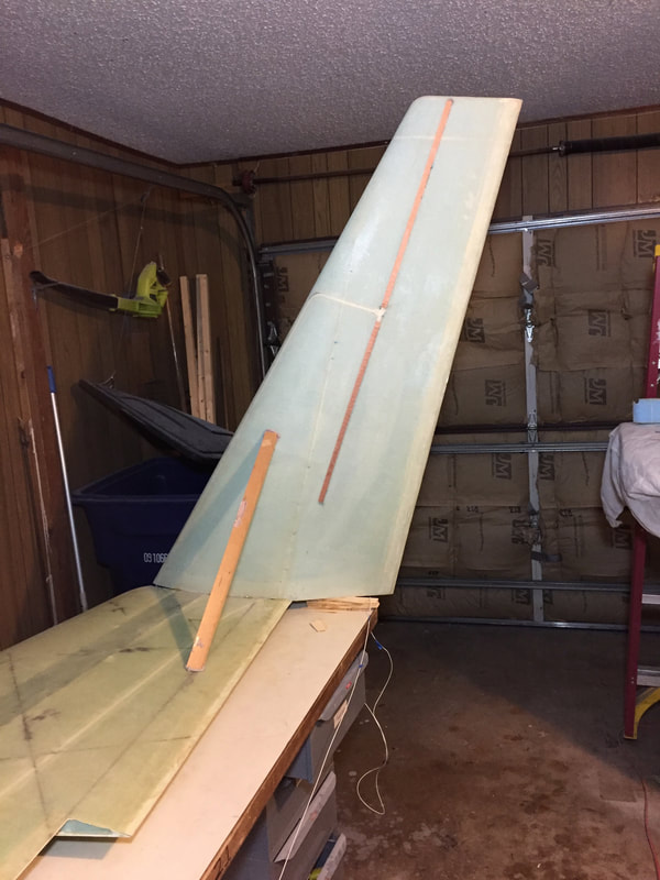
Winglet jigged in place. Check the measurements again after you let go and again 10 minutes later and again 30 minutes later, to be sure it's not moving. I found no movement and was quite relieved! At this point there's not a lot holding this in place. I mixed some flox after an hour and made a nice fillet on the seam where the 5 min epoxy dabs were to strengthen things until I could do the subsequent layups.
|
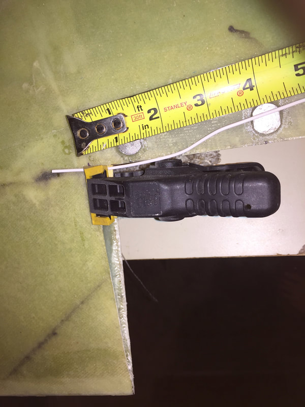
Clamping the 22 ga wire at the inboard aileron reference point. This allowed me to work all three measurements easily on the other end of the wire.
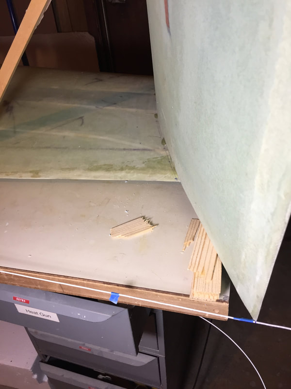
Little black mark on the white wire just to the right of the blue tape is the reference length for the lower trailing edge of the winglet. It's hard to see in this picture, but there's another mark to the right of the other blue tape further left on the wire, and this is the mark for the leading edge. Easy to swing the wire around to the 3 points for accurate winglet positioning.
|
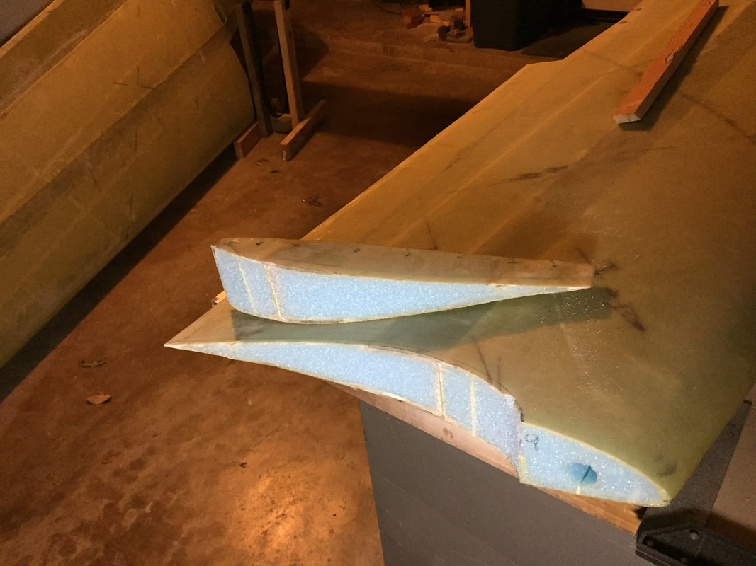
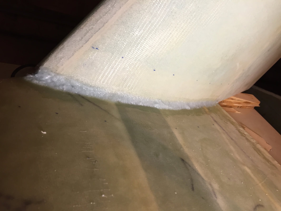
Top Winglet Processes:
With the wing flipped upside down, I could do the layups prescribed in Steps 4 and 5. Before doing all these layups I also worked on carving the upper winglet to receive the internal bellhorn pieces I'd fabricated per the pdf file for this Rutan/Puffer sanctioned modification. The 8 and 9 ply layups take a while to do well and require some pre-fitting of foam wedges, so insure you are prepared before you get epoxy mixed up.
With the wing flipped upside down, I could do the layups prescribed in Steps 4 and 5. Before doing all these layups I also worked on carving the upper winglet to receive the internal bellhorn pieces I'd fabricated per the pdf file for this Rutan/Puffer sanctioned modification. The 8 and 9 ply layups take a while to do well and require some pre-fitting of foam wedges, so insure you are prepared before you get epoxy mixed up.
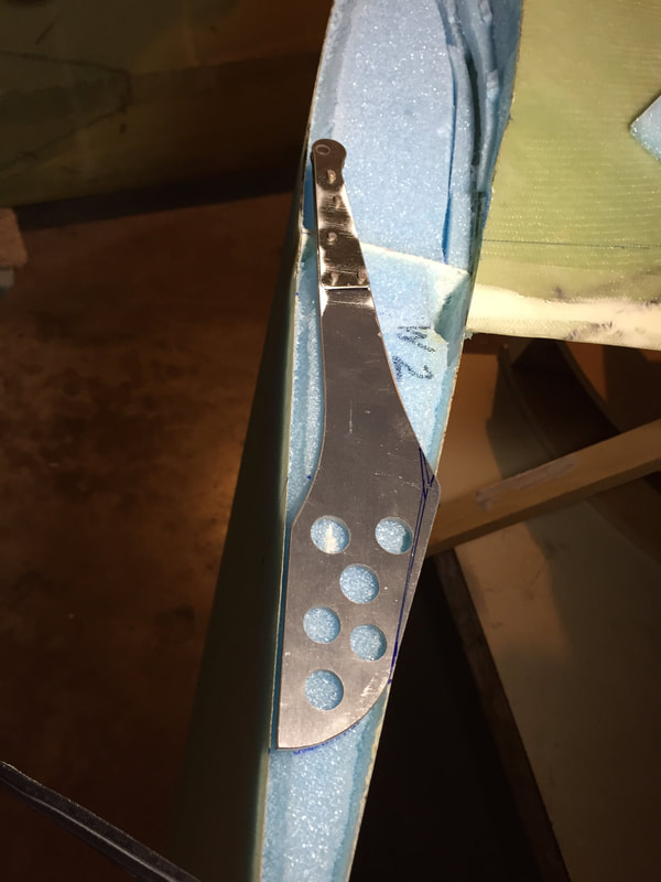
trial fit of my internal bellhorn, showing where I needed to trim it to fit inside the winglet skin (with allowance for the glass pocket it would sit in).
|
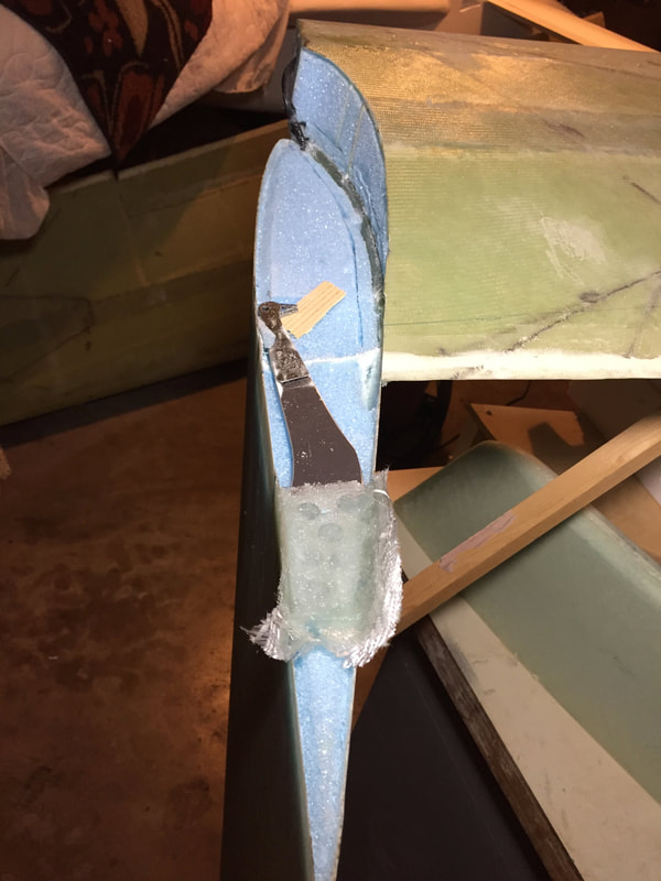
bellhorn glassed and floxed into pocket. It's hard to tell with out looking from several angles, how it's tilted up slightly towards the leading and inside edges of the the upper winglet, so that the rudder cable will pull the tip of the bellhorn directly towards the conduit. I fitted a thimble to help set the "aim" of this line. The glass on the edge is later trimmed.
|
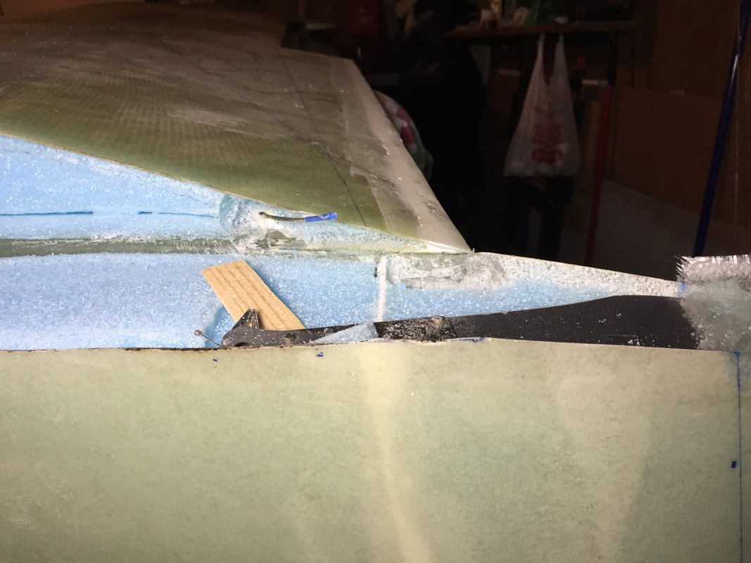
You have to carve into the wing foam and trim back the rudder cable guide to make room for the thimble and nicompress fitting. Running the cable through gives you a good idea of what's needed and helps with alignment of the bellhorn.
On the right side of the picture you can see where I'd marked the pivot line for the hinges. It's important to reference this line when figuring out both the placement of the bellhorn and it's angle, so that the thimble movement to the conduit is "in the plane of the bellhorn"
|
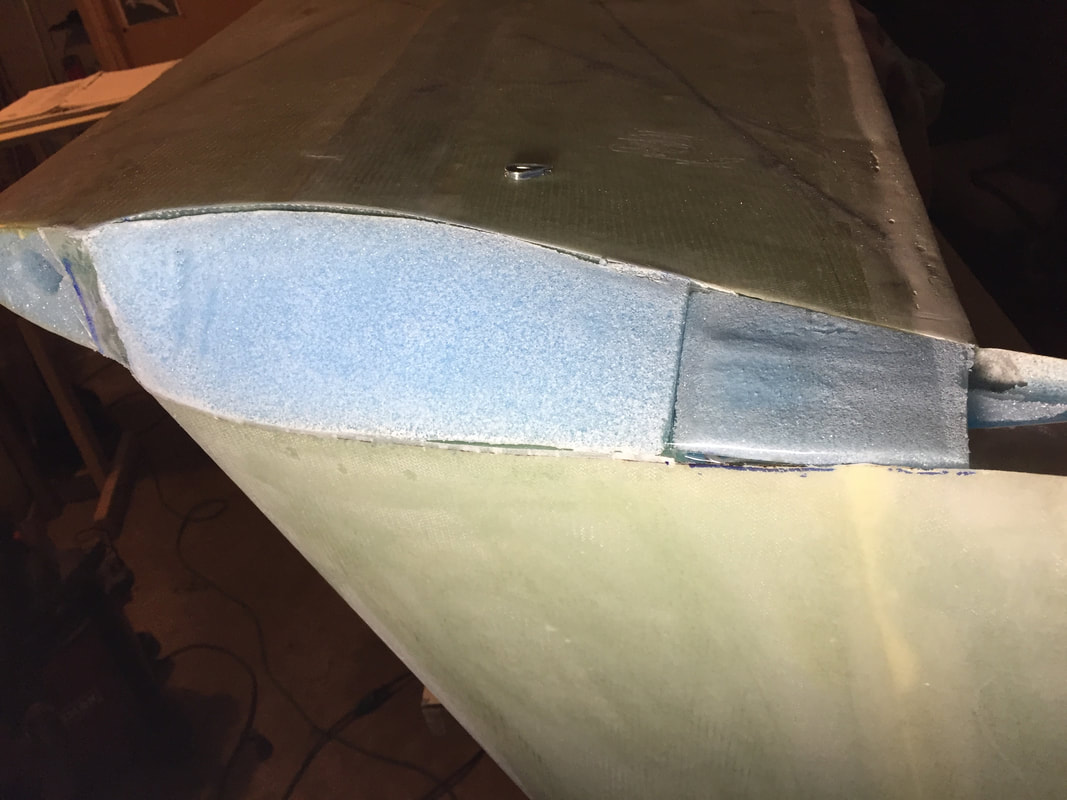
Layups 1 and 2 are successfully completed here and I've trimmed the foam block in preparation for layup 3. I made a dummy foam piece and covered it with packing tape (aft of the main blue foam piece) which will allow me to do full width layup 3 without touching the internal bellhorn (which you can see coming in underneath it from the right). When layup 3 is completed, I'll break this sacrificial foam out and remove it leaving the layup 3 bridging to the outside skin. This might not be required, but it means the layup remains like the plans, even with internal bellhorn.
|
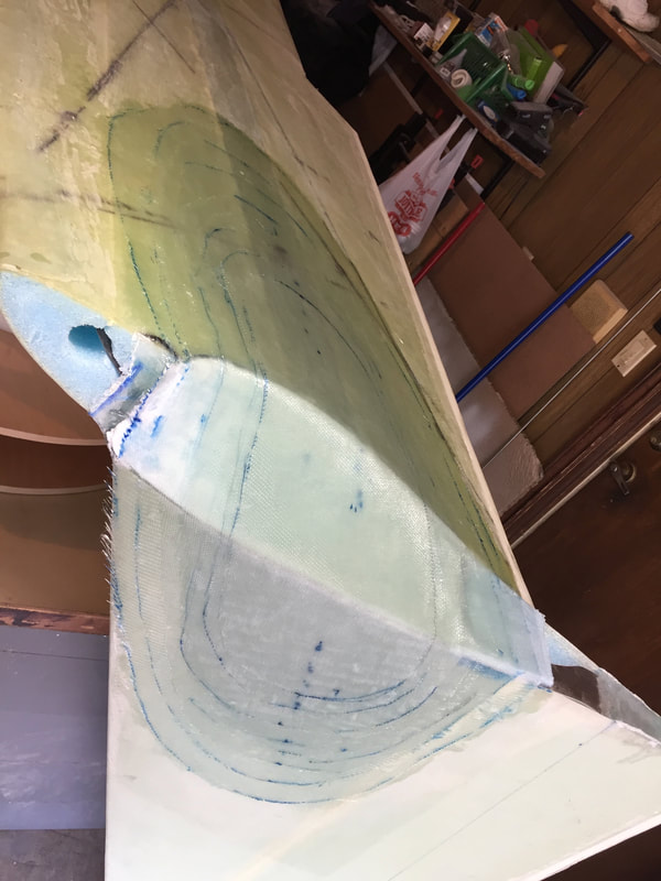
Layup 3 completed
|
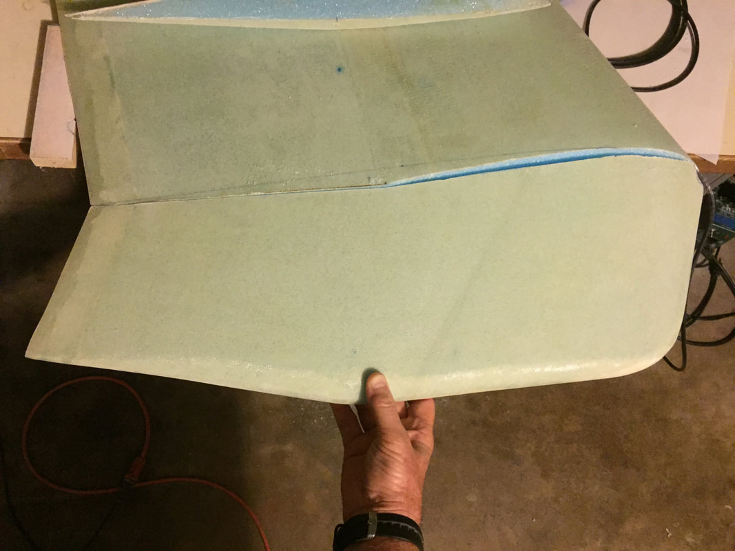
Getting the lower winglet to fit the complicated geometry left over after completing layup 3 is not trivial. I first did a little trim on it to better fit the winglet after it's been cut with the M-20 template, but BEFORE it was attached to the wing. I did this on the L side pieces first since they were sitting idle, and then repeated the the cut on my R lower before taking the next step ->
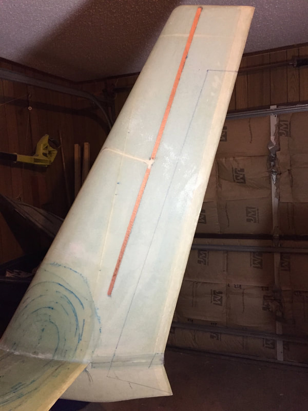
Last step of attachment: flip the whole thing back right side up, remove the jigging brace and apply layup #4 to fully attach the winglet system. I've done prettier layups than this, but it's got all the plies properly oriented and will be very strong.
|
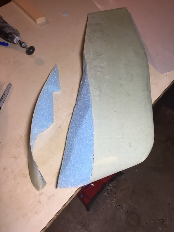
I couldn't find good instructions for how to cut the lower winglet so I used a LOT of eyeballing and marking on the inside edge, before finally cutting and trimming it to fit reasonably well. This is a look after the initial big cut, before trimming the foam.
|
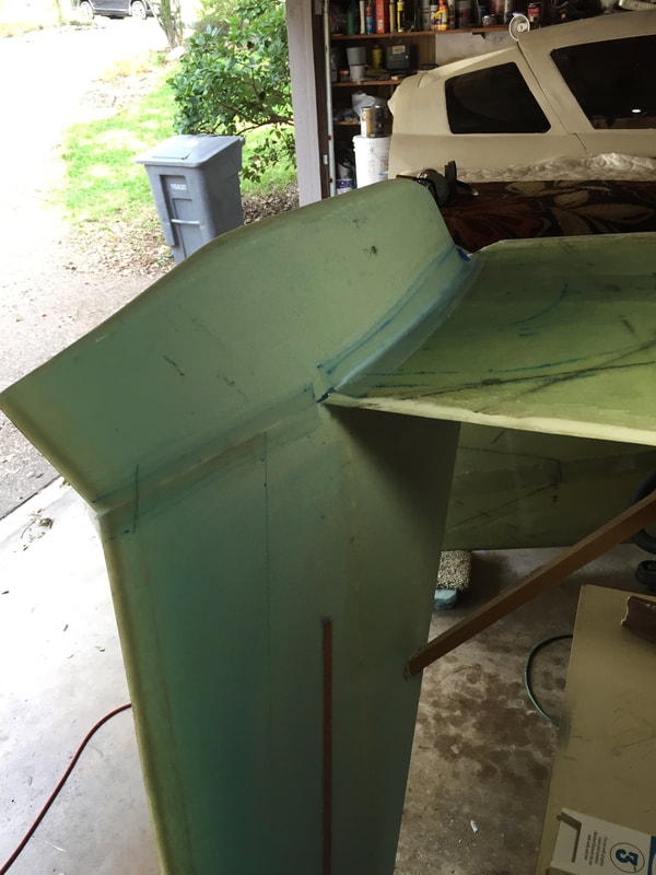
I used 2 plies of BID to attach the lower winglet because I just wasn't comfortable with only one ply. I used a 3/8" radius fillet on the seam with the wing lower skin too.
|