Chapter 13.1 - Nose Gear, Brakes, Landing Light, Skid Plate
|
|
I inherited the strut, fabricated NG-30's, Wilhelmson electric retraction system, and bottom/sides tapered to F-0. The NG-30 and sides were built for a 6" nose extension which means much of the work needed for Ch 13 guided by but dimensionally adjusted from the Plans. I note below where adjustments were made. The NG-30, bulkheads, and sides were built to plans specification/spacing and had been done with 1/4" spruce plywood rather than foam for added strength. The sides and bottom foam were shaped thicker than plans as well, with the specified 2 ply BID skin inside and out. I did use vertical laser line to check alignment of the fuselage which was within 1/8" on all bulkheads accept F-0 which shows an offset of 3/8" to Port (the pilot's side). Further measurements once I flipped the fuselage over (to work on the Nose Gear) indicted that the NG-30's shared a slight offset as well (1/4" at the NG-6 pivot point. This was disappointing but given the castor on the nose wheel and decent alignment of the strut with NG-30s via the NG-6 pivot axis, I decided that this was also acceptable (being an angle of less than 1/2 degree on the significantly rounded nose shape) and the good centerline for the rest of the fuselage. I will pay attention to the rudder and aileron trim in ground and early flight testing to determine if some adjustment is needed to compensate for this small nose angle or not. Post flight note: this was absolutely a non-issue. there is no unusual trim required in flight, and there is no pull left or right when on a level surface without crosswind.
|
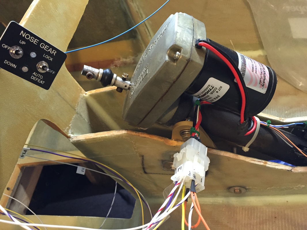
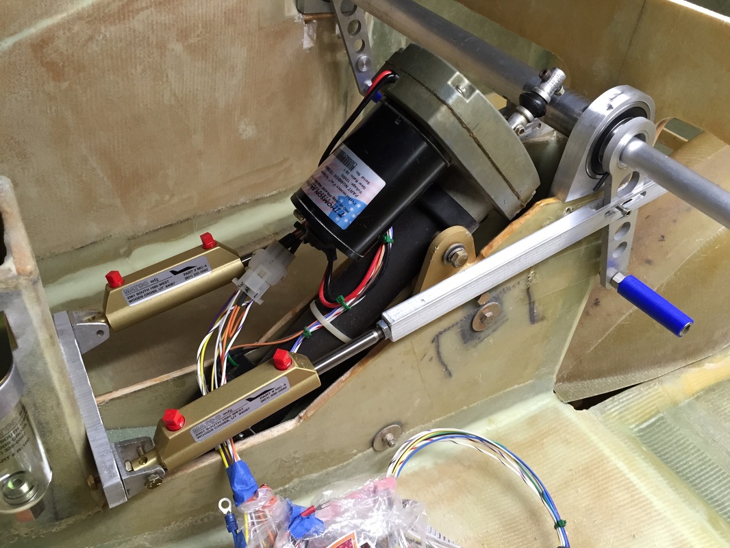
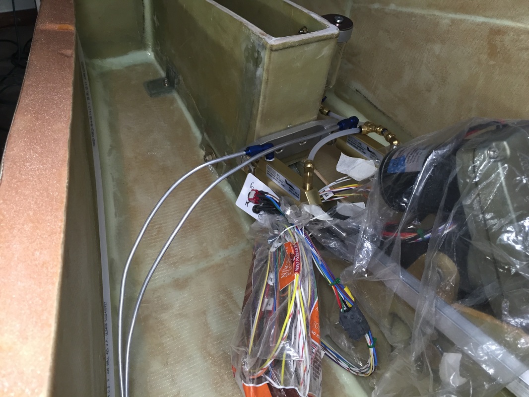
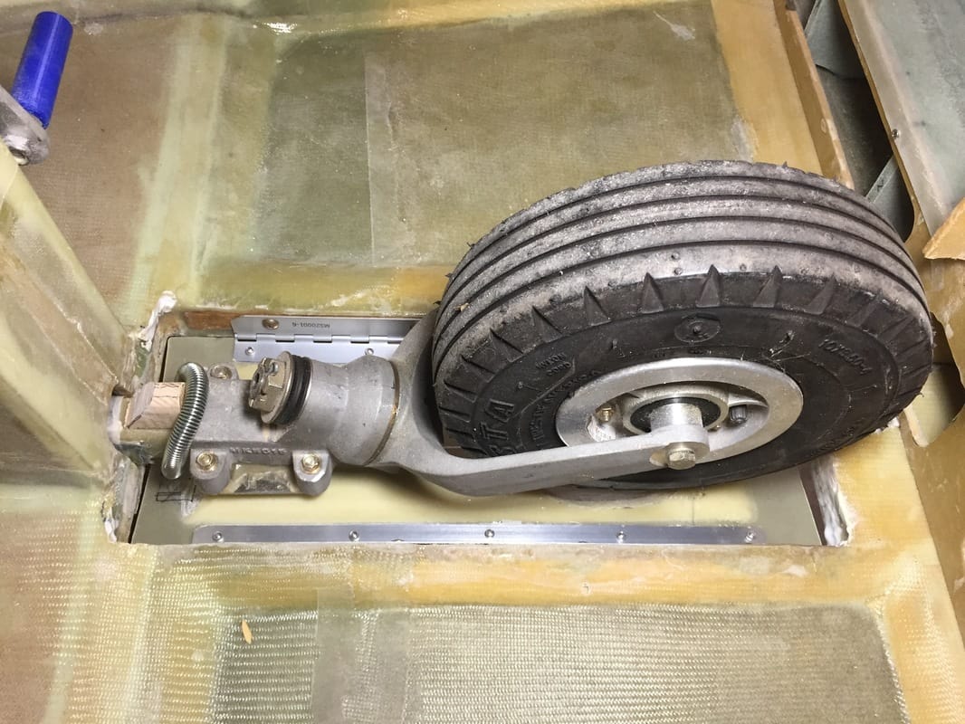
Nose Gear Retraction System: The first thing I worked on in Ch 13 was getting the nose gear setup so the fuselage could be supported on 3 points (Main Gear and Nose Gear) while also having full retraction functionality. I have the Thompson Saginaw Ball screw Performance Pak, ordered from Custom Product Design (the Wilhelmson System). Another motivation for working on this first was that we were having a cold February, with limited warm time in the garage for epoxy work. The nose gear as received, didn't retract all the way and had not been connected and operated electrically yet. Debugging this allowed me to become familiar with the full electrical circuit, adjusting the limit switches, and checking the mounting and alignment of the system. Following the wiring diagram worked fine once I correctly understood the numbering of the 9 hole connectors (P1 connector shown in figure to the left, and there's another P2 connector like it). The electrical diagram gave clues with the wire color and the electrical diagram also showed that port 2 and port 3 had two and three little ridges above them which I found eventually when I held the connector in the right orientation - not being an electrical guy. Be patient, the wires come appropriately labeled. Double and triple check the wiring then power it up: I used an old 12V battery charger and had none of the troubles mentioned online from new "smart" battery chargers. I kept the current rating on my charger set to 2 amps, which was fine (I had the fuselage supported with a saw horse under instrument panel). Big smiles when the actuator worked fine up and down and the limit switches as well.
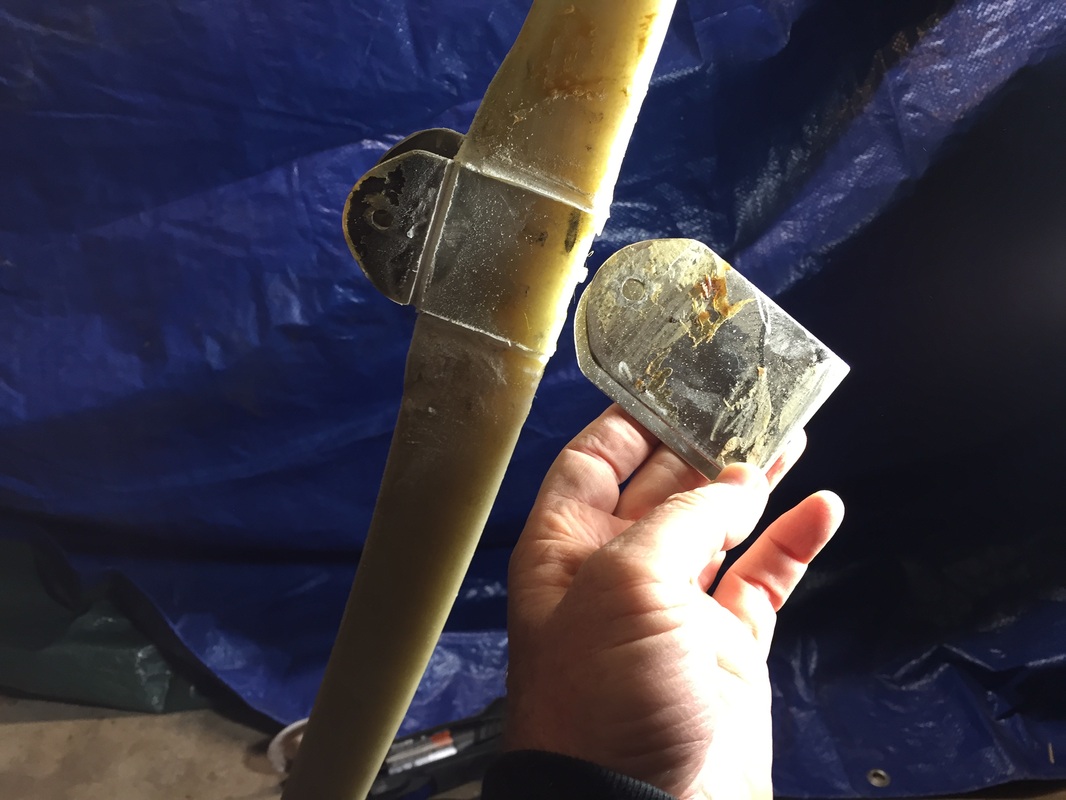
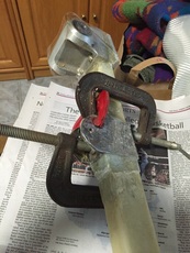
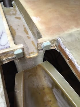
Ultimately I needed to shift the MKNG 3 and 4 bracket up on the strut so that I could get full retraction within the allowable actuator stroke. This wasn't hard after I'd gotten advice from Bulent Aliev and David Pierce about using a heat gun on the metal parts to slightly soften the epoxy below. I used the gun for only about 2 minutes working evenly around the bracket parts and avoiding blowing directly on the fiberglass. Tapping lightly with a hammer downward on the MKNG3/4 where the actuator connects (obviously with the actuator disconnected) when I noticed it loosen. The metal was too hot to hold your finger on, but was not so hot I could not touch it for a second or two. I gave it another 20 seconds of heating while taping and it was clearly un-bonded all around (see figure to left MKNG right after it came off). At that point, no heat, just tap the pieces off, shift them up (the friction fit was good enough to re-connect with the actuator and fine tune until the "up" and "down" positions were within spec. I then floxed the brackets back on the strut in the new position (moved up 1/2 inch). See figure with clamps holding the brackets in place - checked by putting the bolt through the brackets with the clamps on and tight, then remove and clean the bolt with MEK so it's ready to use when this goes all together. This job was generally messy because you want good flox seal everywhere, but also tight fit. I also used this opportunity to remove the MKNG-6a tapered roller bearings and re-greeze them (they'd been stored for about 7 years), even though they looked and felt good. I also marked the actuator limit switch edge angle on the inside of the NG-30 box so I could later figure out where to open the Strut Cover (SC in figure 45 of Ch 13). Because David had built a nose section that's 6" longer than the plans nose, I also discovered that the featherlight SC was not quite long enough to cover the strut opening I later tried extending it and cutting the opening a couple of different ways to allow the actuator to come through and the strut to fully retract, before finally abandoning this part all together and using another method to close off the interior of the strut well as shown below in Step 8. |
Step 6: Brake Pedals
Shaping and glassing continuous load path from the bearing shelf to F22 and the side walls forward of F22
View of brake load path to master cylinder with slots in push-rod at pedal for independent rudder movement
|
Lots to write here... I followed the design of Bernie Siu and adapted it to the thicker nose walls that I've got. Thanks to Butch Cunningham for his help with water jet cutting the pedal cranks, and to Chad Kassem for his amazing welding of the cranks to the tubes after I'd pinned them.
Unique adjustments I made compared with Bernie's fine work were the following: a) I used 6061 tubes instead of 4130. I did some quick calculations and the angular displacement difference was less than a couple of degree's which I don't think my feet will be able to discern. Machining Al in general, is easier, which is a plus for me since I'm doing all of it with the exceptions noted above. Later Note: About 2 years later, when more familiar with Cozy's, I became a little concerned with the angular displacement difference between the left and right pedal, and re-fabricated the left pedal combination in 302 Stainless Steel. This is the one with the smaller tube. Post flight I have no problems with the braking system and don't notice any issues with left/right braking. Since you modulate the pressure on the brakes to get the steering/stopping you visually want, it really doesn't matter if the angular displacements are exactly equal. Good building practice to try and make them equal, but don't obsess over it. b) I used a larger bearing on the big tubes than Bernie used based on the thicker outer diameter of my Al tubing. I like Bernie's bearings more, but all needle roller bearings are oversized for this application of small angle movements. c) I tailored the crank arm designs slightly for my 1/4" thick Aluminum material and the larger Al tubing sizes. I wanted to have at least 3/8" thickness around the outside of the tubes for welding. d) I used 3/8" Stainless Steel bolts for the actual foot contact bars but made them only 4" long to leave room for foot stretching particularly for the co-pilot. I can adjust this later if I want something longer. I 3D Printed the blue plastic covers which fit over the bolt shaft and hide the cap screw head. e) I only used 3 bearing supports since they are so massive and well connected to the fuselage. The center support is on the pilot's side of NG30 and attaches with two bolts, just like Bernie's. The outboard bearing supports are secured by bolts coming up through a 1/4" high density plywood shelf that is glassed into the sidewall just forward of F22 bulkhead. I carved out almost all the foam in these bearing pocket areas as shown, and did significant blending of the curves back behind these bearing blocks to provide good BID glass coverage and load transfer into both F22 and the nose side sandwich areas. f) I modified slightly, what Bernie used for the sliding connection to the brake cylinder. I used a solid 1/2x3/4" Al bar and tapped the end for the brake piston end (with a lock nut) and then cut two slots in it up near the crank. The vertical slot captures the crank arm side to side, and the horizontal slot is the guide for 10-32 bolt which is threaded into the crank. When the pedal is moving through the rudder only arc, this bolt is sliding in the slot. When it reaches the forward most end of the slot, the bolt then bears against the bar, and further movement of the pedal forces the bar/brake piston into the brake hydraulic cylinder to actuate the associated brake. |
Step 7: Master Brake Cylinders and Brake Lines
View of the hard break lines I used and how they are bent to allow small amount of flexure for the very small movement of the cylinder on it's hard mounted forward pivot (see also the pictures above)
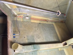
View of hard brake lines behind the forward setback, and pass through main gear forward buikhead.
|
Conventional installation here with following exceptions. Both brake cylinders share a single reservoir. I also ran hard tubing from the master cylinders all the way back to SS flex line at the Main Gear bulkhead, which finishes the run to the Matco triple piston brakes. In the last picture to the left, you can see how I secured the hard brake lines with fiberglass guides that I filled with RTV/silicone to allow for vibration. There is at least 1/4" separation between the hard tubes everywhere, and 1/8" clearance at least between the tubes and the fuselage wall. I'm using AN through bulkhead fittings to go through the forward main gear bulkhead and switch to braided stainless steel from here down to the calipers.
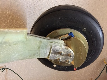
SS flex line connection to caliper
|
Step 8: Completion of Nosegear
|
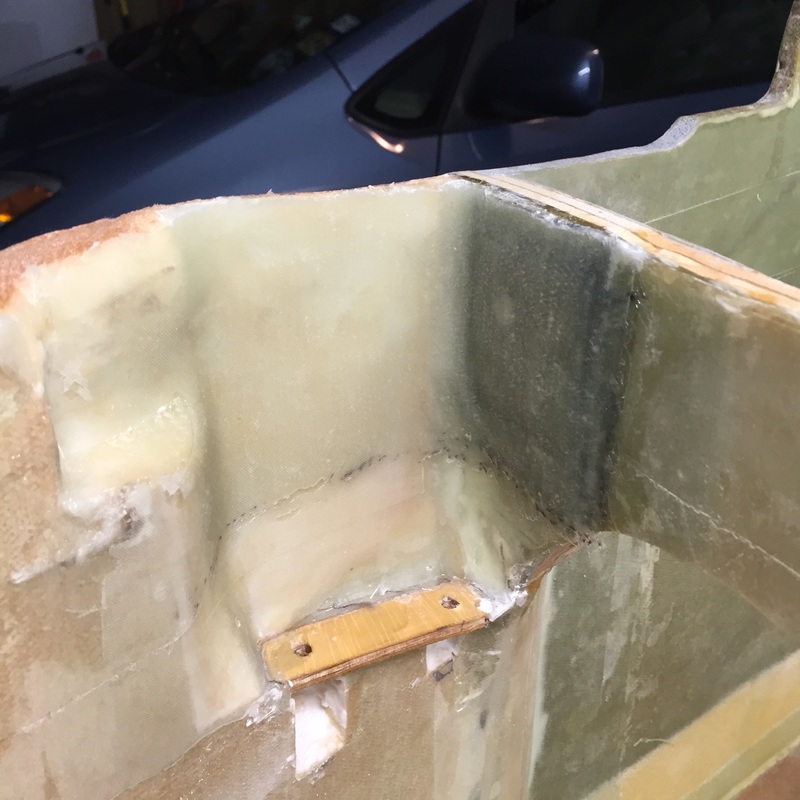
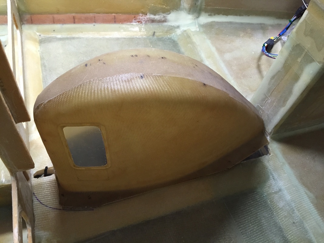
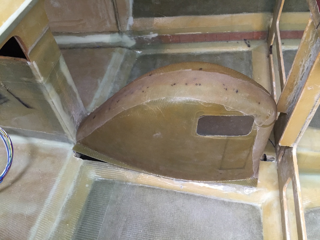
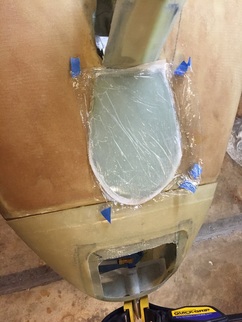
Closing the Strut Well: I tried the featherlight piece and it just didn't work well with the amount of retraction I have in the strut to get the wheel all the way into the well. I chose to close off the well with fitted 3/8" flat sandwiched foam left over from fabricating the arm rests (see picture). Because my nose section is a little longer, this area looks a slightly different than most Cozy's, but I'm using the same approaches it's not hard to recognize the similarity.
I followed the plans for the wheel well windows but oriented the windows differently on each side based on view angle assessment I did sitting in the cockpit. See pictures to left. Nose Wheel Strut Cover and Doors Used Wayne Hicks' method on the strut cover and Nose Wheel Doors. See pictures below and reference Wayne's site. 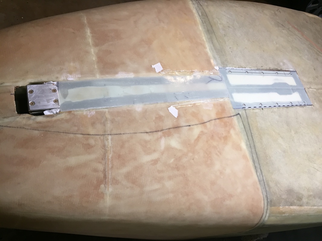
An early picture of the 2ply BID layup I did inside the strut well (the upper portion of picture), when I found that the featherlight part would not work for me. I'll get a better explanation of this documented later, but the just is that I press fit 3/8" PVC foam in the well, and used it to support the BID layup both in front and back of the hole for the strut actuator. The hole will have to be dealt with later with some kind of boot or something... I'm studying what others have done to figure out what makes since with my different arrangement inside NG-30.
|
|
Update to Nose Wheel Doors and Finish of Wheel Well:
About 18 months later (Dec 2016) I returned to this, as I was nearing completion of Ch 21 Strakes because I now was thinking about both interior paint and electrical wiring. It now seemed appropriate to get the nosewheel retraction finished up so I could glass in the well and clean up and paint the interior (cleaning the look) of the nose interior prior to wiring. This started with removing the doors and pop riveting/bonding small metal pivots for a spring to hold the doors open when wheel down and pull them up when retracted. See the photos for details. I also cleaned up the interior and flox/BID'd the perimeter to make it water tight. I also formed two thin ducts (1 UNI) around the lower portion of the wheel well to carry warm air from the heat duct exit between the wheel well and the instrument panel, forward to the feet. These will be glassed in later in the finishing stage, but here's a look at how they fit around the lower portion of the nose wheel well. 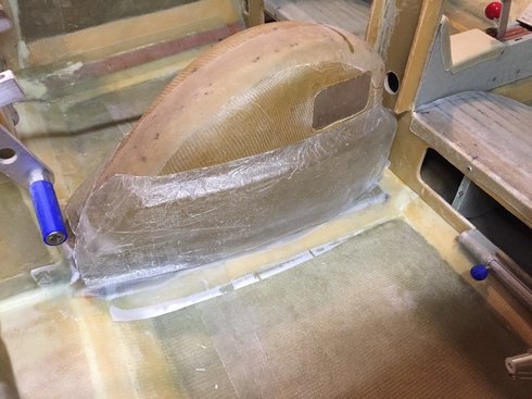
Wheel well glassed in (PP still on) and heat duct skin resting in place (not glassed on yet or exit holes cut near brake pedal positions)
|
Retracted Position (see spring wrapped over metal portion of strut).
Lowering position: spring pushes doors out. Close examination shows the metal spring pivot plates riveted to the doors. These were made from piano hinge material.
|
Step 9: Pitot & Static and NoseCone/Landing Light/Ballast area
|
Followed the plans using the ACS pitot tube in the nose with nylon tubing back to instrument panel. This tubing is easier to run and no less capable than the prescribed aluminum tubing. Because the foam thickness in the nose wall sections is larger than normal, I'll probably bury the pitot feed line in the wall where it goes by the brake pedals to eliminate clearance issue while insuring the slope requirement on the feed tube downwards towards the nose. Static tube is exact to plans.
|
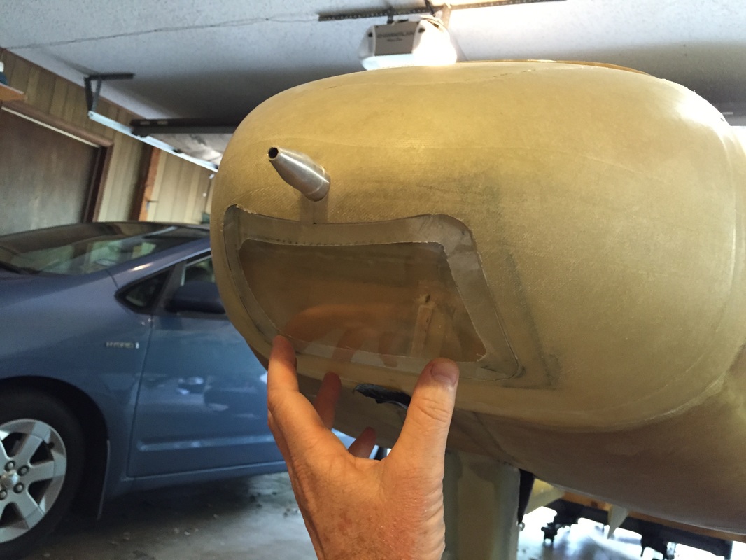
Nose Cone and Landing Light:
|
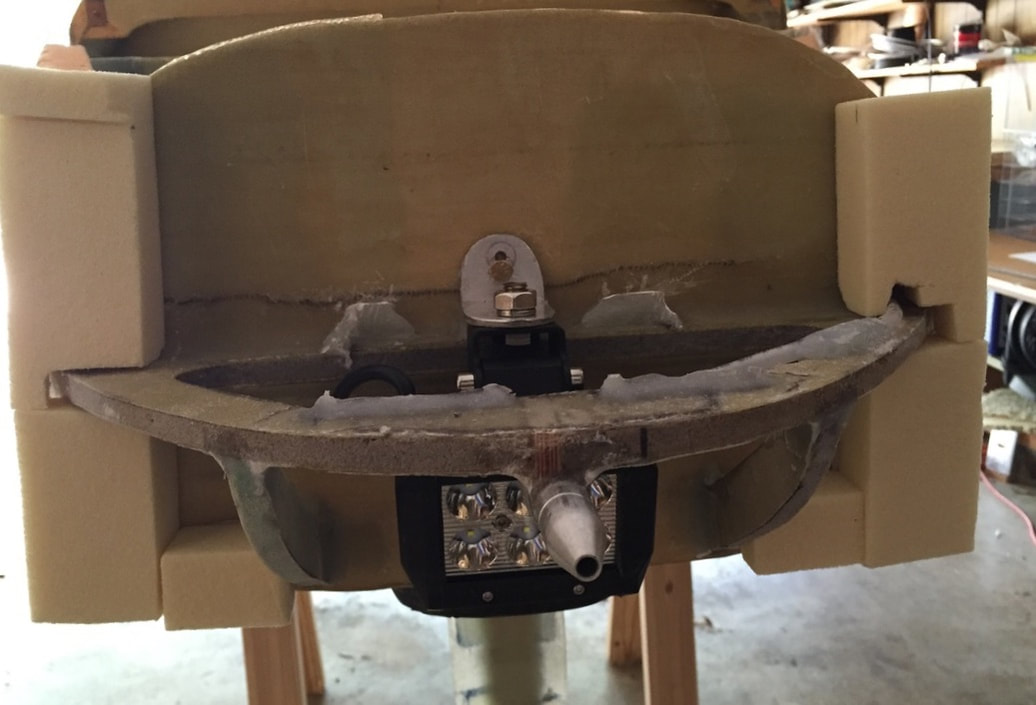
I packaged an LED landing light in the nose cone and also implemented some floxed barriers to make it easy to ballast there with the lead weights I use often in the build. I'll have good notes and pictures here of making the nose cone access door, the landing light window (following Siu and Hicks) and the steps I took to improve the fairing in of the featherlight nose cone to my longer nose profile. More to come...
|
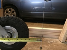
Skid Plate:
Building up the base 16 BID plies in conformation with the nose forward of the landing strut.
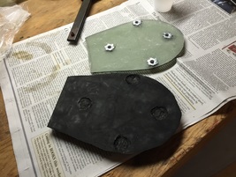
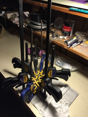
Flox bonding rubber to contoured glass substrate. Always cool when you get to use a lot of clamps...
|
I designed and built a replaceable skid plate following the general approach of Berne Siu. I did not glass over it, I just primer and painted it when I painted the fuselage. See comment below: It has been tested and worked fantastically!

Could not help including this, posted by one of the flyers in the group. A constant reminder that there are only two groups of canard flyers: Those who have had a gear up landing, and those that WILL. So do a good job on the skid plate! LATER Note: I had a gear up landing in Phase I while getting distracted in the landing pattern, waiting for the audible "Gear" warning from my Dynon system. This skid plate performed great and all I did was paint over it, as it had 3/4 of it's rubber thickness left. DON'T get distracted from your checklist/routine in the traffic pattern!
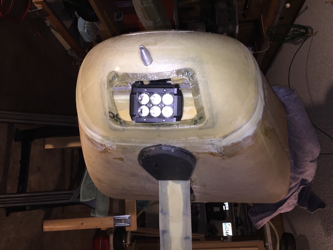
View of the nose with window, landing light, pitot tube and skid plate. Landing light replaced in Phase I testing with a smaller/brighter one.
|
|
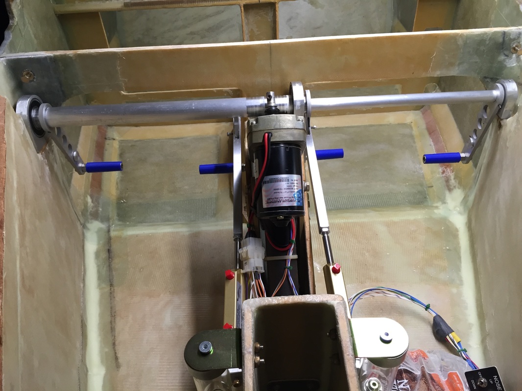
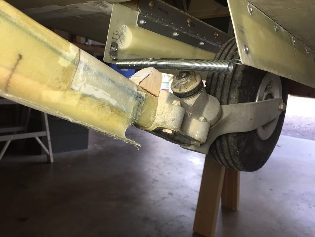
Nosegear Manual Extension Linkage:
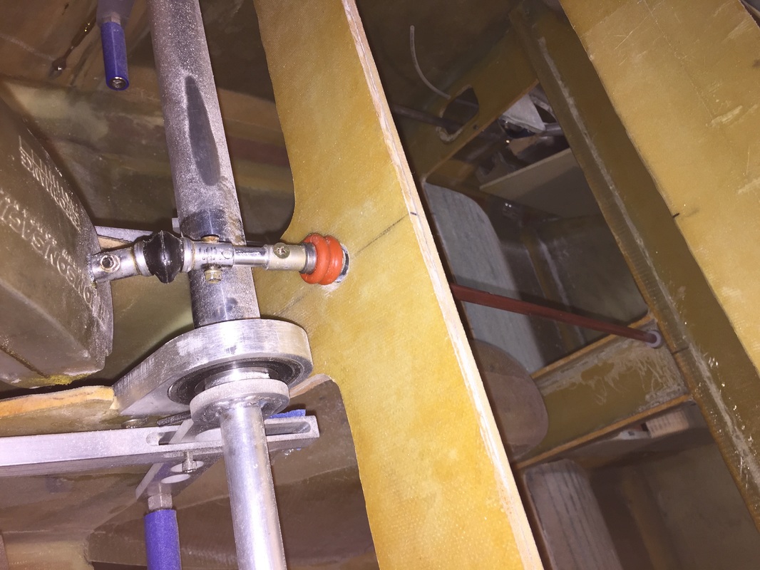
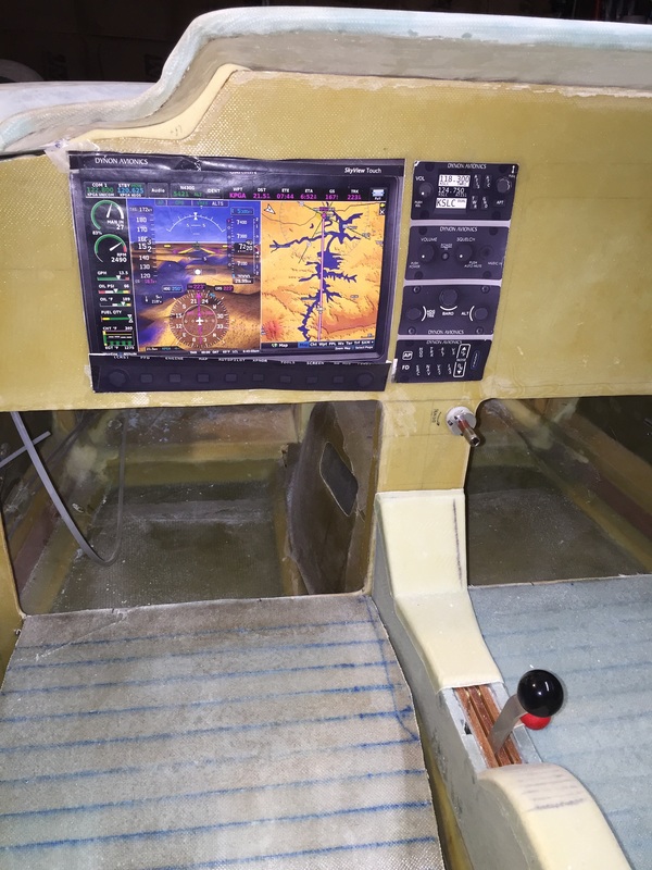
Because I have a slightly longer Nose Section and the Hanging Brake system shown previously, I needed to come up with a custom linkage to allow me to manually crank the nosegear down in an emergency where the electric gear motor isn't working. I used a long 1/4" extension David provided with his project, and 2 universal joints to make the turn above the brake torque tubes as shown in the figure to the left. I used nylon bushings fitted in F-22 and the IP to support the extension and keep all the universal joints running straight. Each bushing was 3D printed and drilled to provide a nice low friction but firm movement. It should be noted that as the nosear retracts, the angle at the first universal (the black one the picture) changes by a few degree's There is enough give in the linkage to accommodate this, but it did require some re-fit, and ultimately I had to shave 1/4" off of the support bases of the brake pivot tubes to lower it and provide plenty of clearance with this extension linkage. If the electronic extension doesn't function, I'll have a 1/4" socket wrench that fits the extension that's shown coming through the IP (just below my "paper radio stack" in the photo to the left, and I'll just crank it down. |
More Ch 13 work on the Nose Top and Canard Cover in Part II Page (see "Chapters" Menu at top of this page.