Chapter 20: Winglet Fabrication
|
|
I started work on Ch 20 as I finished up Ch 16 for 2 main reasons:
1) The first is that I have the Eureka foam cut for the winglets in boxes that are about 4 years old and the cardboard is starting to rot. That's not a big deal except that I'm having to move these boxes around in my house from different rooms and storage spaces as kids come and go to college, and each time they move they become more damaged (these are not small boxes). I wanted to reduce the storage volume (extra foam) and also get these winglets built and glassed so they are less vulnerable to dings in their foam form.
2) I'm also improving my skills with the glass and was ready to take on an airfoil in total, since I'd gotten the wings and canard in skin form from David Pierce. The weather late winter/early spring in Austin was unusually warm (perfect low 70's for working with epoxy as well, so it seemed like a good time to do this.
I plan to get the winglets built and stored until I get a hangar. Then I'll attach them to wings, cut and finish the rudders and continue on. Packing trailer to move to hanger is WAY easier without the winglets on the wings.
|
Cutting and Shaping the Cores:
Because I had Eureka numerically wire cut foam all I had to do was micro the sections together. I didn't do the 1" upper tip in urethane, but shaped the tip just as specified in plans. I saw other builders questioned this as well and felt this portion of the rudder was not going to be a performance breaker. I will not change anything about the rudder, so it will have very similar control authority. I also will maintain the same antenna geometry, it will just be 1 inch lower than plans. If anyone reading this has flight experience with similar configuration, I'd appreciate a message on it via my contact on Welcome page of this site. 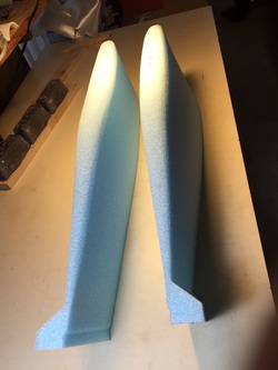
When the plans say round the bottom of the lower winglets they mean the bottom after you have cut off the triangle in the lower-back and rounded the forward corner. I think all builders get this pretty easy. Only I had to over think it and ask the forum... No harm. That's what I like about the Cozy building community and it's neighbor the Canard building Community.
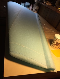
If you look close you can see where the micro associated with the hard shell is curing on these lower winglets (there's no hard shell on the foam near the trailing edge of the back piece so it's more blue). This un-"shelled portion is going to be cut off and faired in before glassing this side as shown in photo to the right of this one.
|
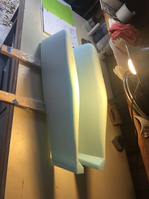
Upper winglet cores getting micro'd together. Note that even Eureka cores are not perfect after they've been in the box for a while. I cut sections of the packing foam with leading edge profile and used them with the table clamps and the weights using on the main core to get a good seam between the cores during bonding phase (careful alignment check on the ends). I was really glad to be working with Eureka cut cures though!
Upper tip after shaping and before hard shell.
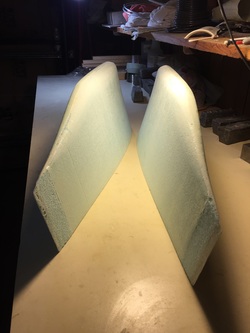
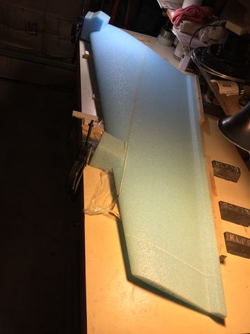
lower winglets with Trailing Edge Foam removed and ready for glassing after they get a little hard shell on the foam (but not in the last 1/2 inch where you will do glass to glass bond with epoxy only.
|
|
Glassing the Skins:
At this point in my build experience I'd seen the dialog and adoption by respected builder/flyers about using the hard shell method of skinning foam prior to glassing and it's superior peal resistance, as well as the reduced leaching of micr spheres from the wet micro layer into the epoxy of the glass layers when doing everything at once. So: time to learn how to do it. I started with the lower winglets since they were smaller and in my opinion small boo boo's there would impact performance less than on the larger upper foils/rudders. A good reference for this method is given by a number of very good builders and I'll just repeat the link here: hard shelling. I followed the method and had no problems. As long as you plan for a good sanding of the hard shell when it cures (I didn't have the flexibility in time to pick an optimal partial cure to start the glass layup) the method works great and I felt the quality of the overall layups was extremely good (smooth, clear, no bubbles, and ample ability to move the first layer of fabric without dragging around micro). I will say that this takes more time since there are 2 cure cycles rather than one for each side, but I think it's worth it for the airfoil shapes in particular. Finished the upper winglets per Plans with the antennas embedded as shown to the right. The main tip I feel might be useful to new builders is to plan for digging out plenty at the coax/ferrite coils intersection at the antenna. You really want this to be flush and then micro it over. I used Dremel with a router attachment head to cut the trench for the coax (after hard shelling) and it worked great. I fell really good about how these foils came out. They are smooth and clean and the trailing edges are nice and smooth and strong. I'll need to do a little more fill on the trailing edge where you micro the depression from the Rutan method, and that's fine. Now they go into storage until I go to hangar (easier to store and transport wings and winglets without them being connected). Unless the plan changes later and I need more time at home to work... 3/18/16 |
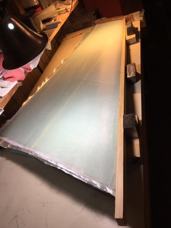
View of typical glassing of upper winglets. Note use of board to get good contact at leading edge (peel ply a MUST or the wood will stick)
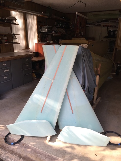
Finished upper and lower winglets with antennas installed and coax ready to thread through wings.
|