Chapter 24: Fairings
I didn't work on the fairings until I had to for the Ch 25 finishing, which meant that it happened more in the normal plans sequence than the other elements of Ch 24 that I'd done much earlier.
|
Strake Upper fairings:
As a part of preparing to do finish work on the upper side of the strakes and fuselage, I needed to get the upper strake fairings completed. This section talks about the shaping and glassing and the next section shows how I created the access for the fuel probes that are buried inside them. Note that it's important to mark where the fuel probes are located where you can see after the fairing is on, if you want to use the method I used. I kept the fuel probe plugs in until I'd finished the fairing and then made an access cavity for the probes and inserted them much as I might do in the future if they needed to be removed. The main reasons for this was that I didn't want to get pour foam on the probe, I considered the frequency of needing to access the probe very low, but I wanted to go through the process of getting access and inserting the probe to make sure I could later get it out without much trouble. Note that I didn't make a removable "door". Jump down there to see what I did and then come back up here, if interested in the shaping glassing process I used. Rather than use a lot of text at this point, I think I'll let the pictures/captions tell the story... |
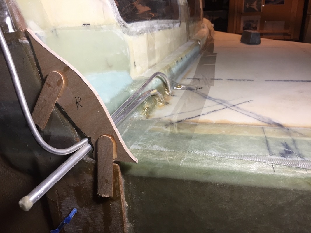
First I re-made the upper fairing firewall shape guides per the drawings in the plans. Also boxing taped the edge where I didn't want foam to stick to the fuselage/windows/strakes
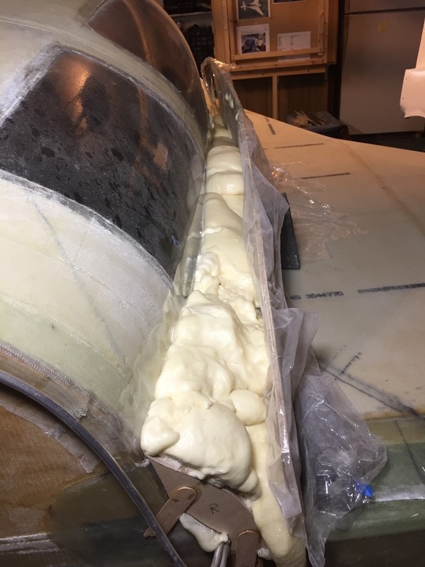
plywood dam with saran wrap to prevent stick, then pour foam...
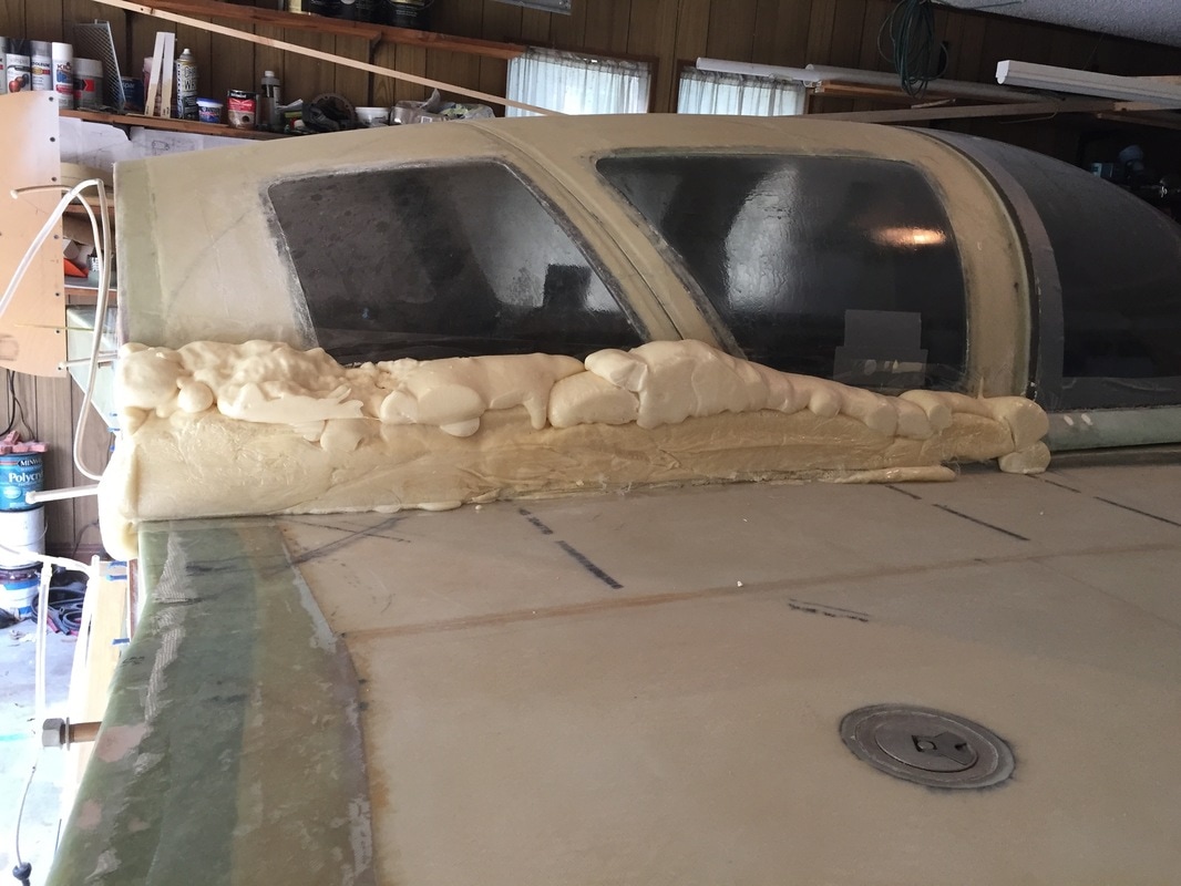
Remove the dam: Ugly!
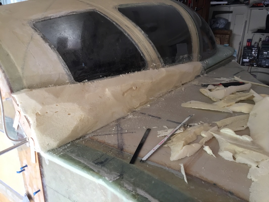
Phase 1: cut big chunks away with hack saw blade...
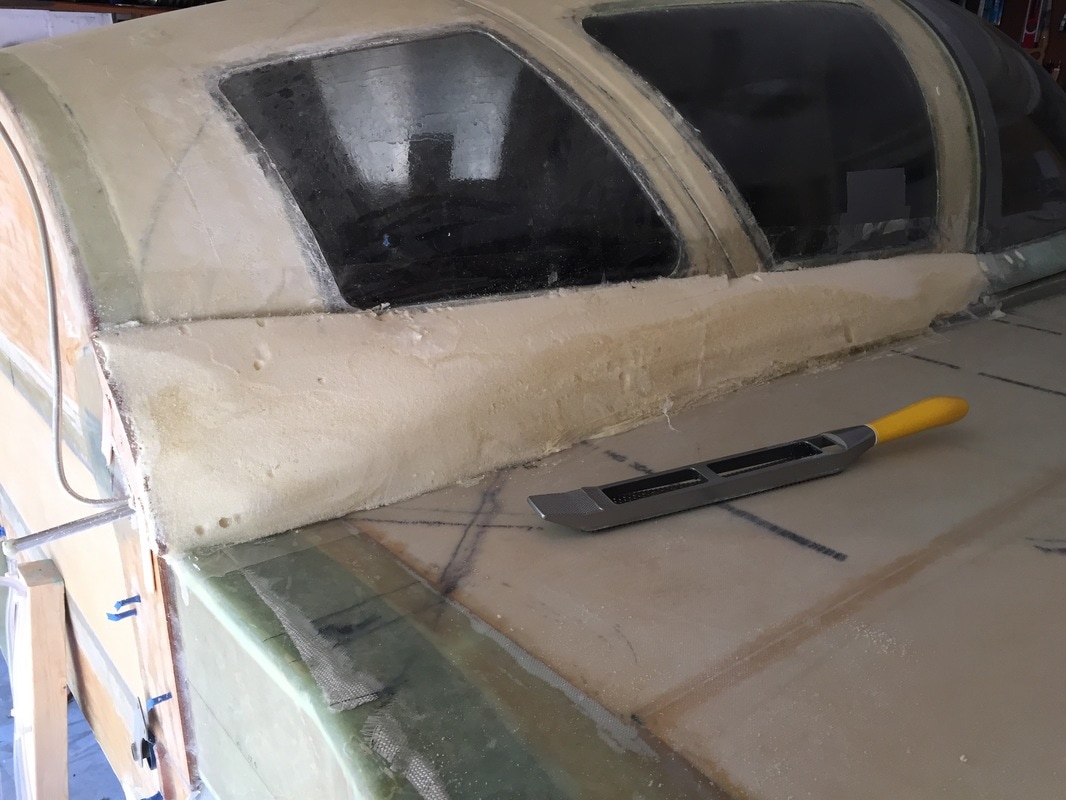
Phase 2: continue shaping with light use of cheese grater tool
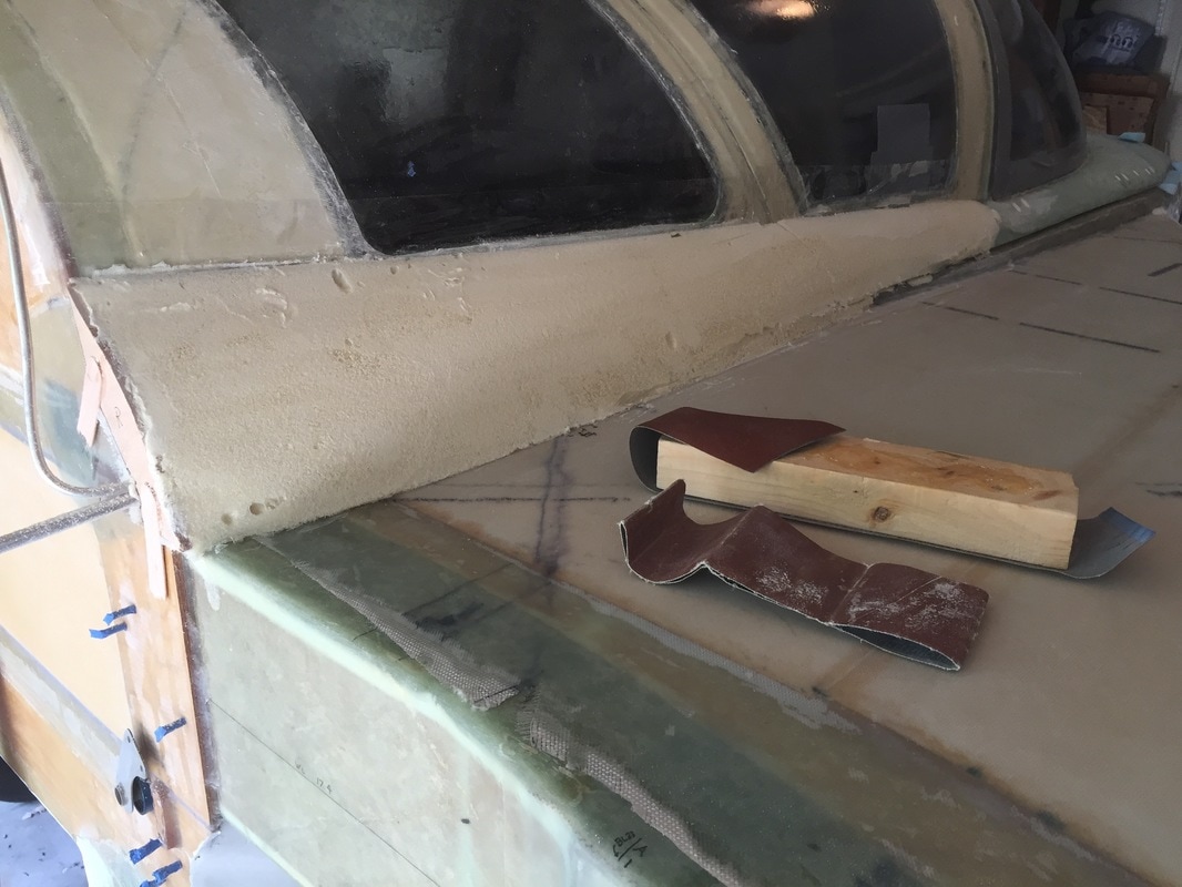
Phase 3: 60 grit sanding... followed (sorry no pictures taken in the several passes with 80 grit to get the shape I was happy with.
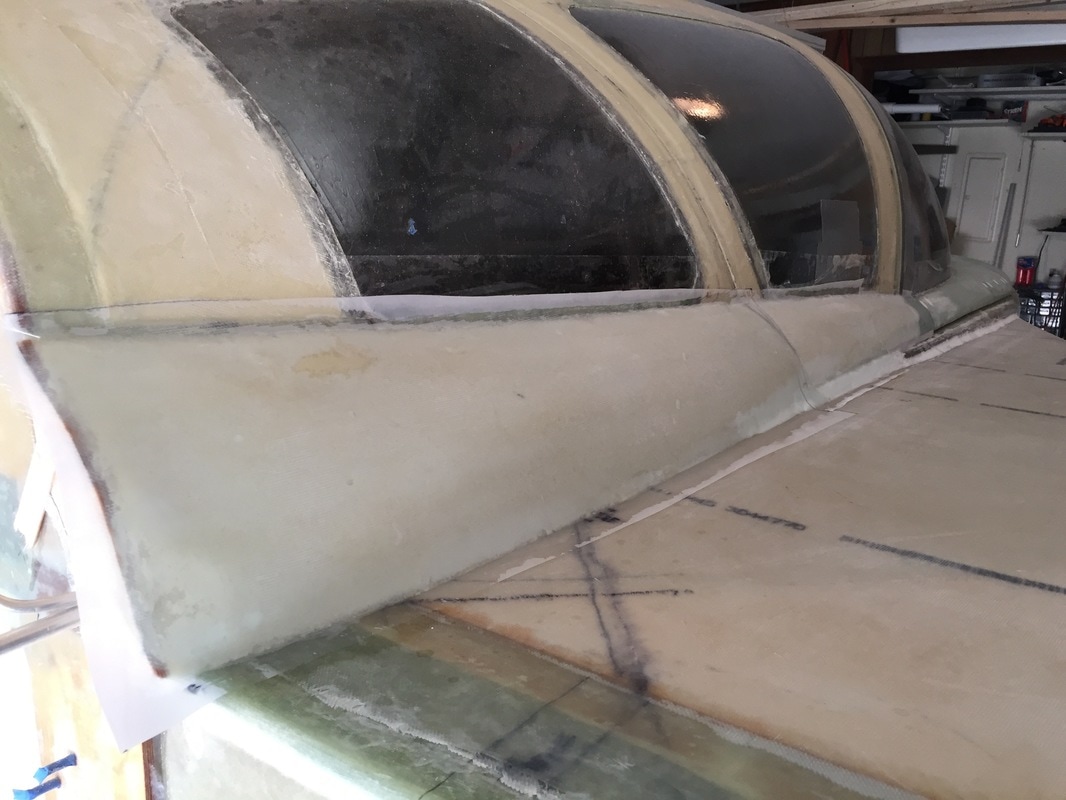
Hardshell the foam, then sanded again, and glassed with good micro fillets, then cut the canopy free on both sides
|
|
Fuel Probes: I'd pre-fitted the fuel probes when building the strakes and fuel tanks, but had left them with a brass plug (see Ch 21: Section IV Misc Completion of Strakes page on this site...). Now that I was covering up their location, I needed to be able to get to them if they had a problem later.
I thought I might need to clear tape over the fuel probe plug to keep it from being a mess when I did the pour foam. It turns out it doesn't matter. I taped one side and didn't tape the other and digging the foam out was equally easy with a dremel. I wouldn't bother if I were doing it again (more steps). I also made a patch of 2 UNI (like I used on the fairing skin) following the method used by Bernie Siu (see his Chapter 24: Section 9 page), but in the end didn't use it. The piece I cut out to access the foam went right back on with good fit, and since I wasn't trying to make a nice looking door, this step was another that really wasn't required for me. I just micro'd the cutout back on and it essentially became invisible as part of the pre-primer finishing process. 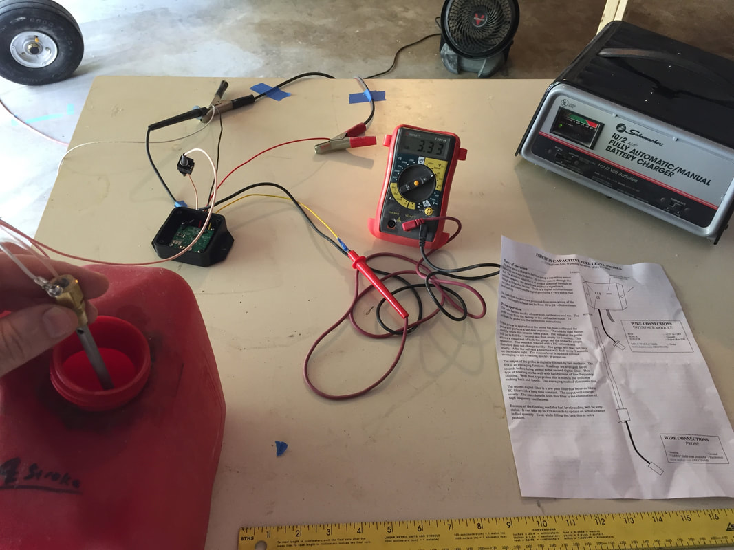
Before installing probes, I did a calibration and check of their response following their instructions. They work, so I'm comfortable burying them now...
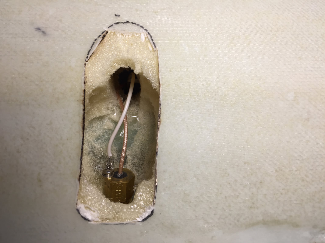
A little more foam removed to allow me to get a wrench on the fuel probe and tighten it down. This also shows the 1/2" hole required to get the fuel probe feed wire connector and ground wire inside to the controller card
|
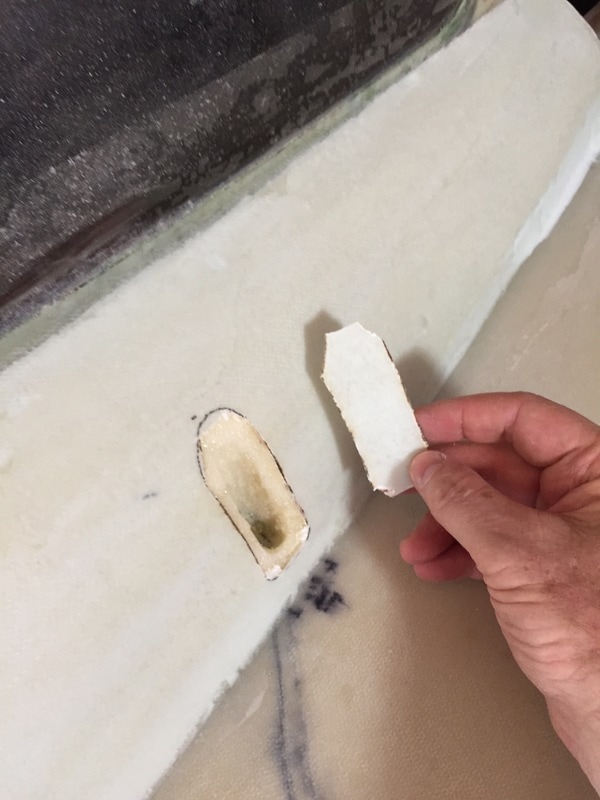
Cutout for fuel probe with a little bit of foam derailed away. I ended up just micro'ing/floxing this piece back on when done. Note the black marks on the strake upper skin to show me where to cut ... made these BEFORE starting the pour foam process above!
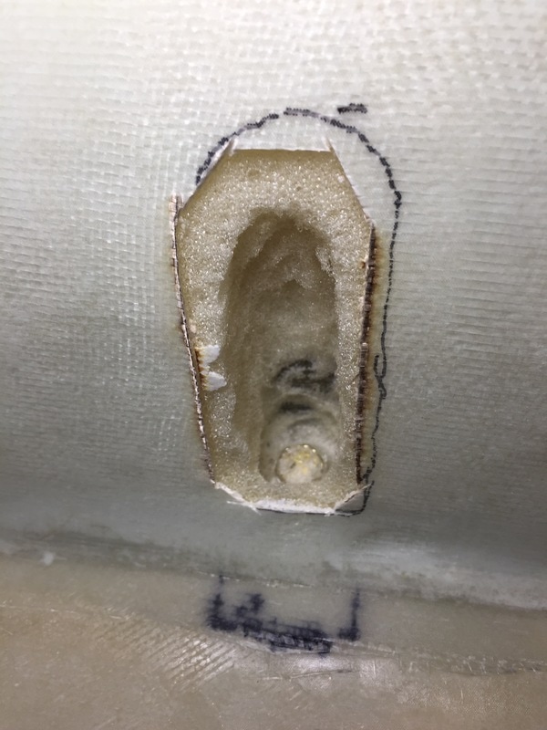
dremel down gently, feeling for the head of the plug and then go around it gently to allow getting a socket on it for removal.
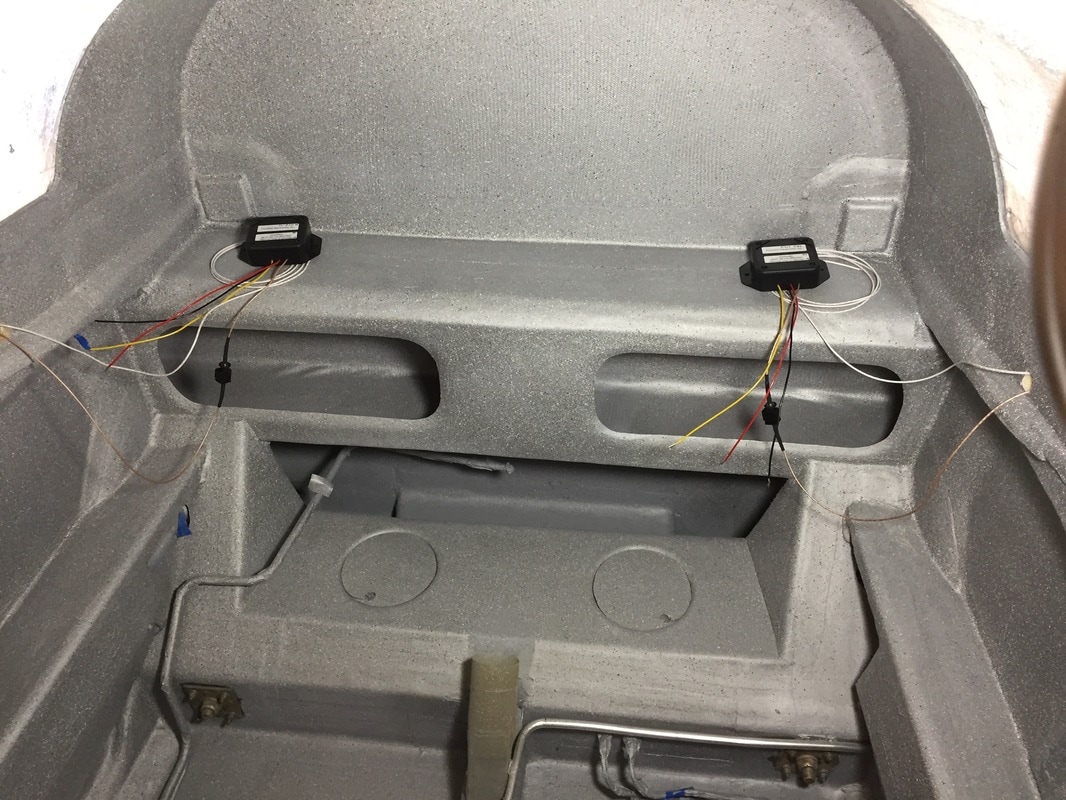
A view when done of both probe controllers connected and awaiting placement inside the fuselage!
|