Chapter 26.2: More Punch List Stuff
The list of to-do's got too long for the 26.1 page, so I'm adding another page here. All this stuff was done effectively to prepare the Cozy for Airworthiness Certification
|
Correct Firewall/Engine Mount Bolt lengths:
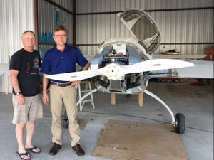
I needed to replace 2 of the engine mount bolts at the firewall (the lower 2) because they were barely showing a single thread beyond the castle nuts, and this required getting the engine lift again from my friend John Nodler, to take the weight off of these bolts. I also needed to be more careful with the engine straps now because I had the CHT probes in and the cooling plenums installed on the top of the engine. To avoid any strap interference with the plenums I built a spreader bar so the lifting strap was vertical from under the cylinder heads. Once the engine load was supported with the lift, the bolts slipped out and new ones slightly longer were used and tightened properly. Here's a picture of Johannes Brinkman who helped me with this (someone has to be on the inside with a wrench in the hell hole while the nuts are tightened from the aft side of the firewall). Thanks much Johannes! |
|
|
ReDo on the Brakes:
I made followed the guidance rendered on the Cozy Builder's Group email list that DOT 5 (not 5.1) was OK to use for our brake fluid and found that I had some leaks in the main calipers. I'm not completely sure that this brake fluid will not work, but in hind sight should not have used anything but the aviation rated brake fluid we can get pretty cheap from ACS. It is also possible that the calipers were leaking not because of a compatibility problem with the DOT 5, but because they have been sitting around without lubrication for over 8 years while first David and then I worked on this project. I had bought new brakes when I started my project (before buying David's project 4.5 years earlier and I decided to just swap the old axle/brake unit for the new ones I'd bought. This was easy and when filled with the aviation brake fluid, I had no leaks. Yea! Since I had the wings and engine on now, I needed a good way to raise the main wheels off the ground for this swap and there were great suggestions from other builders on the Cozy Builders group. You can see the method I used in the pictures here. I also moved the master cylinder reservoir to the highest spot I could get it in the nose so air bubbles would more easily bleed up to it (below). 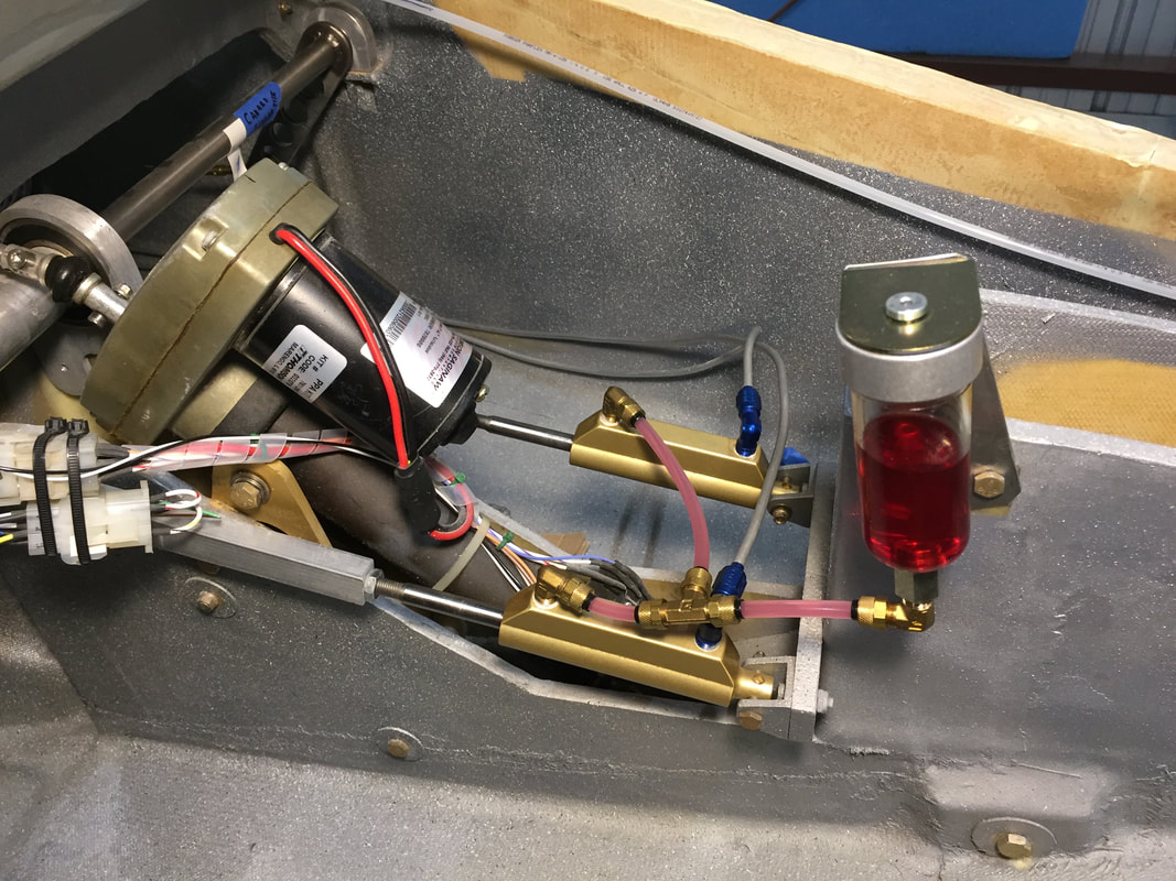
Single shared brake reservoir, high in the nose.
|
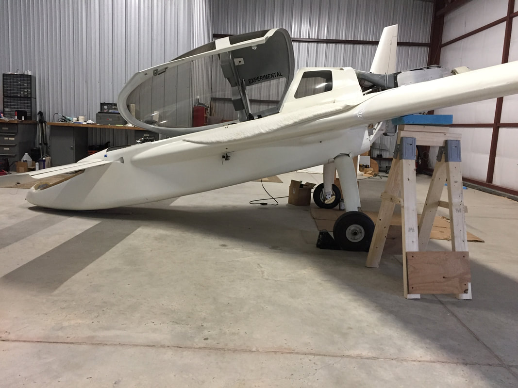
Nosegear UP, drops the nose and raises the spar/wings slightly. Sawhorses with blue foam rested under the spar in this position (see next pic below).
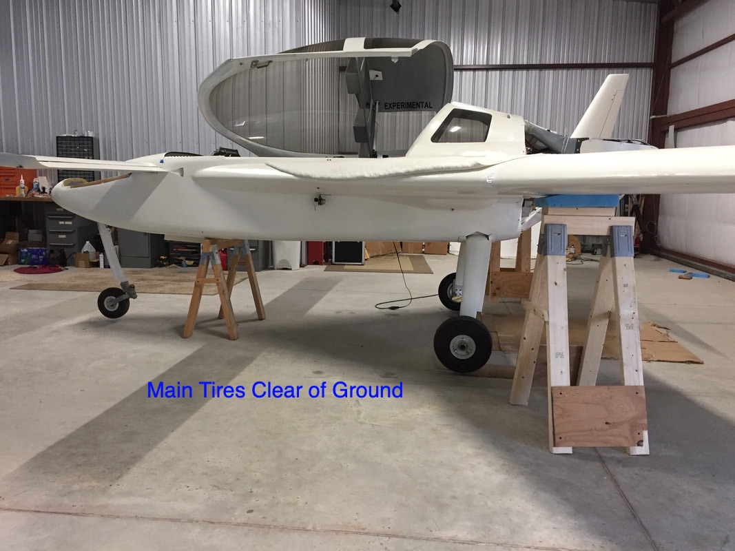
Nosegear lowered - raises nose which puts the main wheels off the ground because the spar/sawhorses are behind the main gear pivot point. I then put a 3rd sawhorse under the instrument panel area for general stability. Nosewheel is castered forward to clear the ground with my standard 3rd sawhorse height. I can now work on the main wheels/breaks safely.
|
|
Slow Taxi Testing of Brakes:
With the brakes now well sealed and adjustments made to springs for good rudder/pedal return to neutral, I could test the system at slow speeds on the ground around the hangar. Here's a short movie of N78CZ maneuvering under it's own power and with both brakes working well. Thanks to Brandon Tapp (N615PM Cozy MKIV) for filming this. |
|
|
Vortilons:
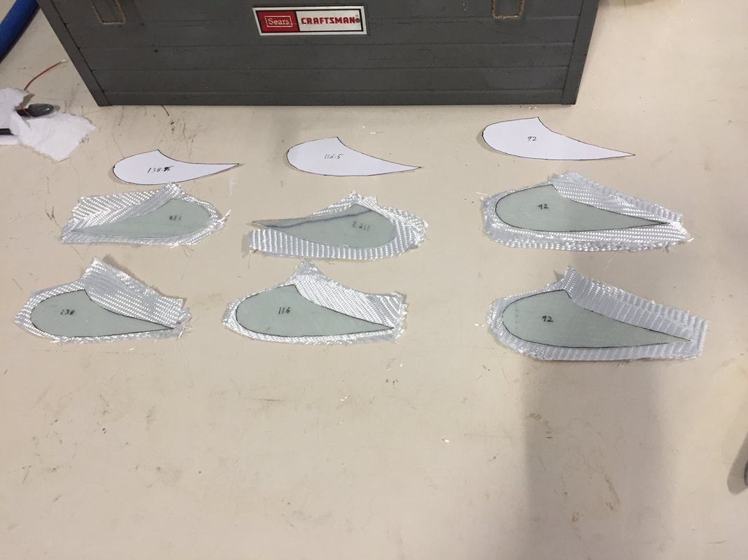
Now that the wings are on (I hope permanently) I'm ready to make the vortilons. These are described way back in Ch 19 for the wings and the pattern is in M-18. I followed process Bernie Siu sent me, since there's not much description in the plans. - measure and mark locations on the wings (laser centerline on hangar floor, then measure the body line offsets in two locations (fwd and aft of wings) from this centerline, then use the laser again to bring the body line up from the floor and onto the wing). - clear packing tape over the marked areas as a release and 2BID the "foot" of each vortilon - layup 2BID sheet and cut out the shapes of all the vortilons - trim the vortilons and confirm good fit with the feet (don't really need to peal feet off yet, but I did, then had to tape them back on) - glass 2BID on each side of the vortilon to the feet (each vortilon is 6BID thick and their feet are 4 BID). - remove trim, and paint, then epoxy the vortilon feet back in place to finish. 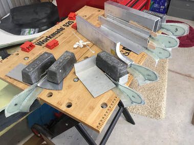
Couldn't keep the vortilons from falling off the wings during the vortilon - foot layup so I pulled the feet from the wings and did the layups upside down on this tabletop. This allowed me to use the metal pieces to hold alignment while not flattening the foot shape that will bond to the wing later.
|
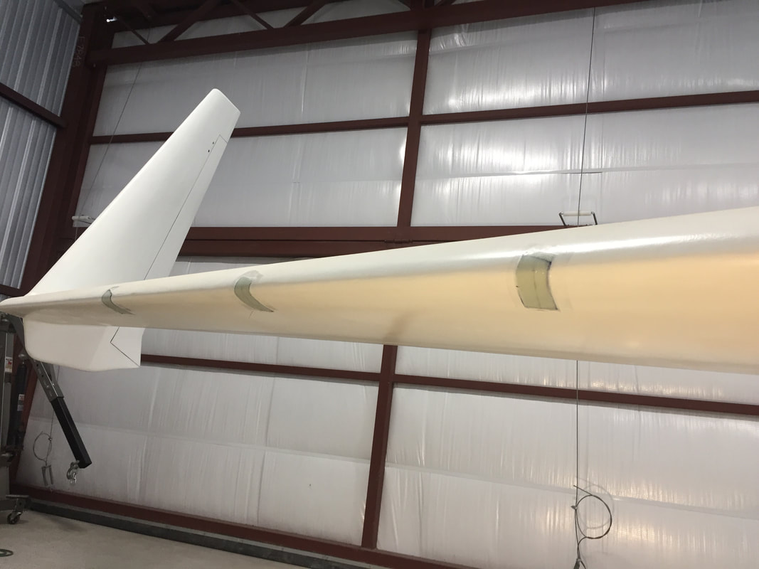
Wings marked (black line visible under the 2BID layups of the vortilon "feet")
4 BID glass to thicken and attach each 2BID vortilon to their "feet". Picture before glassing in place. Later will remove everything, trim, and paint.
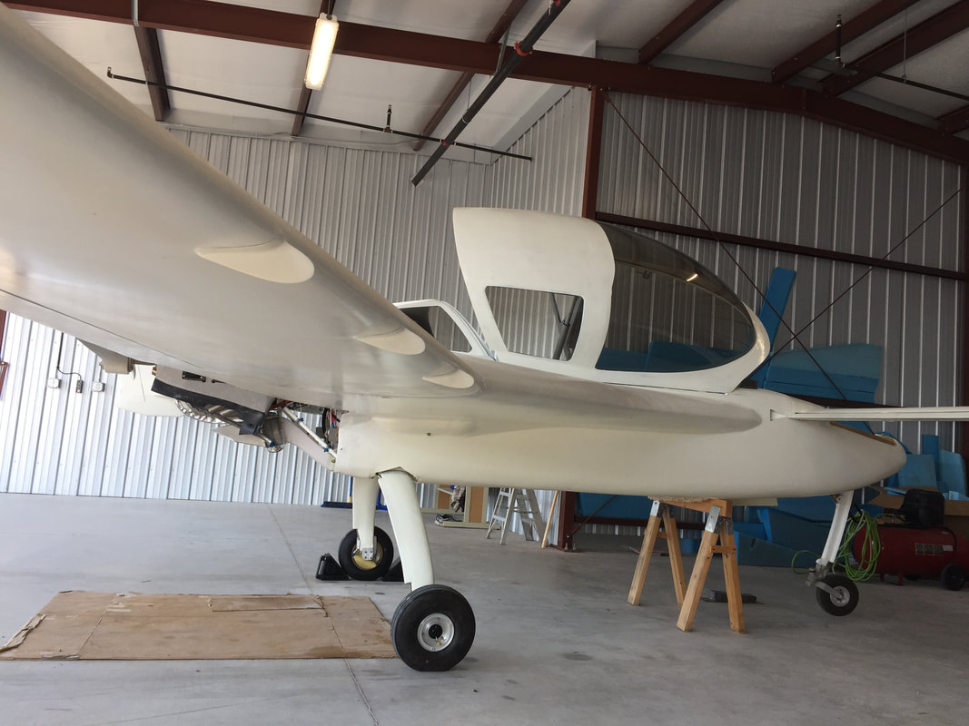
Trimmed, Sanded, painted, and epoxied on. Woo Hoo!
|
|
Emergency Locator Transmitter - ELT:
When I have passengers I'll have to have an ELT, and like most people, I'm installing it prior to the Airworthiness Inspection to be more complete/compliant. I've only done preliminary fit check and am planning to put the device in the nose as I'll need weight there. Because I have hanging rudder/brake pedals the floor is clear up here. The antenna has been mounted behind the pilot seat, where many other Cozy people put it. The little panel switch is mounted low on the IP in the center where it's easy to see. 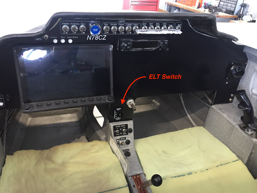
|
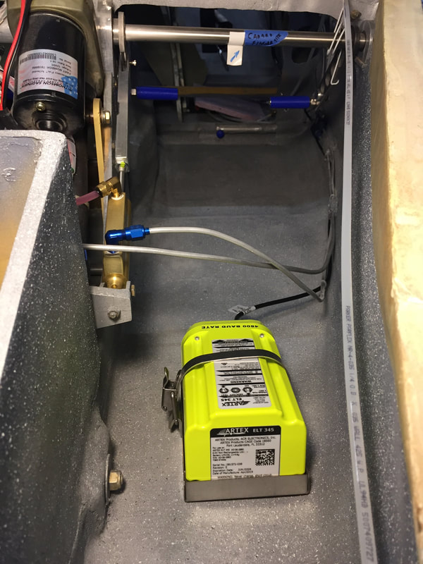
ELT box in nose with antenna coax running along side the brake lines back to behind the pilot seat.
|
|
Ballast in Nose:
I recognized the need early-in the build of being able to put even small amounts of weight as far forward as possible to control the CG, and made provision in the very front of the nose, just above the landing light, for installing two of my lead weights in a secure way. Now that things are approaching inspection, and I've done an initial weight and balance, this need is now real. I opened the little hatch in this area and fine tuned the position of the weights which total to 11 lbs, and now need to have a means of insuring they don't move (they are well supported and constrained on their forward edge, and will get some strap or something to keep them from moving even slightly. I also have a ballast area just behind this forward-most bulkhead and will have an option to load up to 50 lbs of lead there. The pictures here show the partial bulkhead installed (weights loaded over the top of this partial bulkhead) and the 1/4" neoprene lining to help prevent weight movement and distribute loads from the lead bricks into the floor. 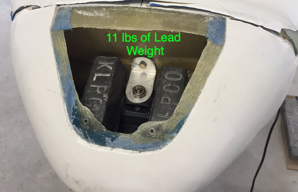
two lead weights: one on either side of the landing light bracket. They are supported on a frame inside the nose above the light and will have securing strap.
|
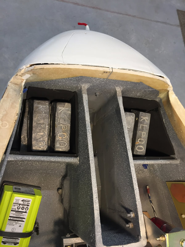
45lb of lead bricks loaded in neoprene lined ballast areas fwd of partial bulkhead and behind the forward-most full bulkhead. Picture taken before the Nose Top has been glassed on, since it's hard to see these compartments through the removable Nose Top Hatch.
|
|
Autopilot Preparation:
My plan all along was to wait until after Phase I testing to install the Dynon Autopilot Servo's. Since I have time while waiting to get my airworthiness inspection with the FAA, I've decided to go ahead and at least get the roll servo mounting bracket installed back in the hell hole and run the control wiring run from the hell hole up to the IP. In part, this was because I want to get the rear seatbelts installed for airworthiness and not have to go back later and remove them and the rear armrest lower panel, which is really difficult to remove and install. As I become more familiar with the Dynon Skyview system in preparing for flight, I'm also better appreciating the safety advantages of the autopilot. I will still do a LOT of flying manually, but being able to link the autopilot to flight plans will have some precision advantages and also enable more attention to be given to traffic/weather, and other things as I grow in flying competence. I'll post more on this as it progresses. As time delayed for inspection scheduling and weather to first flight, I put a little more effort into this since it's not that easy to stop working on the plane... I developed the design for how I wanted to mount the servo's and then made the composite brackets and ran the wiring. The full installation of the servos and calibration occurred roughly half way through my Phase I testing. For my roll servo the bracket is bonded to the underside of the main spar in the copilot side of the hell-hole. It will actuate a crank arm also composite that's the same size as the arm on the servo that will later be fitted on the aileron actuation tube as it passes under the spar on that side. The pitch servo bracket is bonded and bolted to F-22 in front of the pilot and will actuate a composite crank arm that's 1.5 times the arm length of the servo (following roughly the crank design Rick Hall did with his Cozy). In both of these cases, I've designed crank arms that can be inserted and bolted on without sliding the arm over the end of the tube. In order drill/fit the roll crank arm, the aft torque tube (CS 122) had to be removed and then reinserted. I slid the roll crank arm on as I reinserted the tube through the firewall, and was glad that I didn't make it wrap all the way around the tube to allow for the tight space in that area for tightening the bolt/nut. This is a tough place to put the roll servo. It's benefit is that it's in the cockpit and protected from the engine compartment, but it's a really difficult space to work in with wrenches. If you are a big person and/or have big hands, choose a different place for the roll servo that you can access more easily. I wired the servos per instructions and with a reminder from Rick Hall ran the Dynon setup configuration again to enable Skyview to "discover" them. Then I could run through the ground calibration and test procedures to set the motion limits, slip torques, and some other autopilot parameters. Flight testing shows it working in Simplified mode just fine so far. I like the autopilot more than I thought I would, as it allows me to divert more attention to navigation and communication, while still keeping a light touch on the stick. |
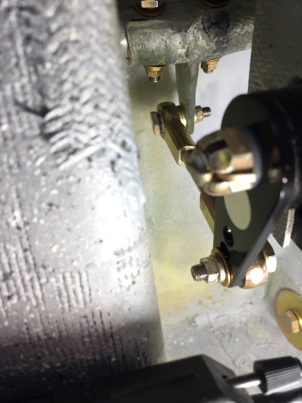
Very difficult to take a picture of the roll servo in the hell hole.
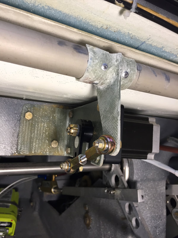
Pitch servo under the canard. It's bracket is bonded and bolted through F-22. The composite crank arm is in place, but not yet attached to the elevator torque tube.
|
|
Propeller Finalized for Phase I:
As noted way back in the Engine section, I'd gotten a loaner prop from Gary Hertzler to use for getting the engine started while Nate Mullins was trying out a number of different props with his UL520is on a Long EZ. Once I had the Cozy fully assembled and brake system was fully checked out I started static max RPM tests and found (as expected) that the loaner was too much diameter (68D x 76P) for this engine. Nate had found that the Hertzler 65Dx76P was the best match for his Long EZ in flight testing and Gary agree'd that it should be good for the Cozy as well. I ordered a silver one of these dimensions, and swapped it with the loaner and static RPM rose from 2300 to 2600, which was very good for this higher RPM engine. Here's a picture of the two propellers. I also confirmed the clocking position of the prop (which was good on the loaner) and marked the prop extension, so that the blades are out of the way when the #1 and #2 cylinders are in the exhaust stroke, so they don't impinge on the propeller. |
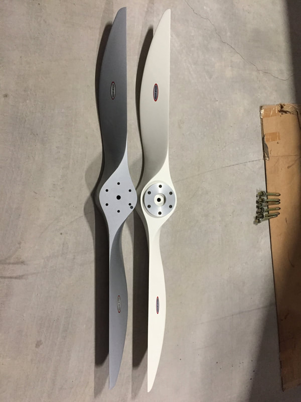
65x76 Silver on left
68x76 White on right
|
|
iPad/Foreflight Holder:
I plan to use the iPad and Foreflight/ScoutADSB/GPS to augment the Dynon display for map view/navigation. Partly this is because I've already learned to use Foreflight in my rental plane experience and it's really a nice flight planning and navigation tool. Because the Scout provides ADSB-IN and weather and together they have their own Dual 160 GPS puck, I'll effectively have dual mapping systems onboard. I think I can upload Foreflight flight plans to the Dynon Skyview HDX as well, so then I'd have redundant navigation tools with at least the pre-flight flight plan. I'm aware that this does not satisfy IFR requirements but is really terrific for VFR operation. I designed a custom iPad bracket that hard mounts to the Instrument Panel. The iPad snaps in and is angled towards the pilot, but readable/useable by the copilot. Airflow space behind it is ample and the only time I've noticed heating problem with the iPad is airplane on the ground with the screen facing the sun. Don't leave iPad in the sun on the ramp ever. I have no problems with cooling in flight, even on hot days. I have a USB power circuit from the VP-X with multiple ports, and a couple maintain charge power to the iPad and Sentry (Scout replaced later with Sentry). Both have their own battery backup power. |
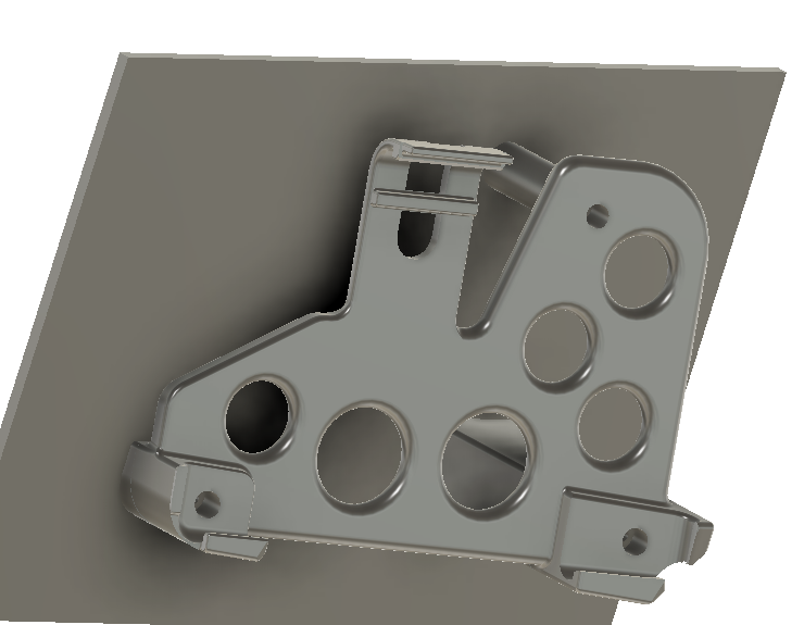
CAD view of the iPad bracket that was 3D printed on a Gigabot printer.
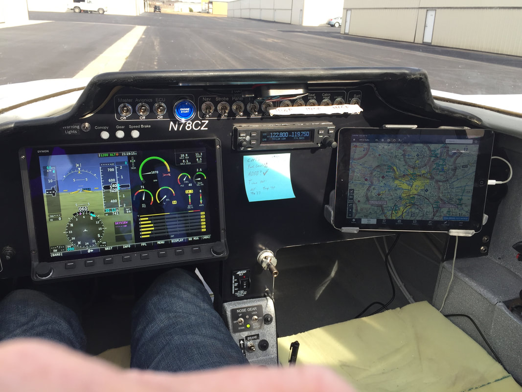
Just after engine start. This shows the Instrument panel as it exists in Phase I testing. The iPad is on the right in the custom mount, and it's powered from a USB power source, that's temporarily under the copilot thigh support. This USB power block also powers the Scout (ADSB In receiver) which is taped to the right side of the canopy, and a separate Dual 160 GPS for Foreflight.
|