Chapter 22: Electrical
Getting Started = Planning:
I started preliminary planning for the electrical system after applying the top skin of the Strakes to their respective T-hats. I have more work to do in Ch 21 Strakes but the electrical system is not simple, and I've not done electrical wiring at this complexity before, so early planning and consideration of what will be needed seemed appropriate.
A few assumptions I started with should be noted here:
I'm planing to equip my Cozy for day/night VFR to start, and grow it to IFR as my fight skills and need develops. This way, I get flying sooner. I won't be flying IFR in the early days with the Cozy anyway. As I develop IFR skills and need, the equipment will evolve, and I'll purchase what makes sense at the time to transition to IFR flight. I will also plan for an autopilot, but I'm not sure if I'll implement the autopilot before completing my phase I flight testing for similar reasons. I'll make sure I have the capacity for these upgrades and they will be part of my continued enjoyment of building after I am flying.
More to come here, I just wanted to go ahead and get this page "up" so I've got an easy place to put things as they develop.
I also want to recognize some great input I received from Neal Johnson who configured his MKIV instrument panel/VP-X in much the same way I'm planning, and he's flying now.
A few assumptions I started with should be noted here:
- 12 V DC Distribution System
- Single PC680 Battery (may add another later, and some systems have their own backup battery as noted below)
- VP-X solid state power distribution box
- Dynon Skyview is likely display but will decide when I price things out after getting a rough design laid out. It has it's own backup battery
- Not sure yet on the COM/NAV/GPS/ADSB/Trans/Intercom... (actually lots to learn in this area).
I'm planing to equip my Cozy for day/night VFR to start, and grow it to IFR as my fight skills and need develops. This way, I get flying sooner. I won't be flying IFR in the early days with the Cozy anyway. As I develop IFR skills and need, the equipment will evolve, and I'll purchase what makes sense at the time to transition to IFR flight. I will also plan for an autopilot, but I'm not sure if I'll implement the autopilot before completing my phase I flight testing for similar reasons. I'll make sure I have the capacity for these upgrades and they will be part of my continued enjoyment of building after I am flying.
More to come here, I just wanted to go ahead and get this page "up" so I've got an easy place to put things as they develop.
I also want to recognize some great input I received from Neal Johnson who configured his MKIV instrument panel/VP-X in much the same way I'm planning, and he's flying now.
Refinement of Planning
Despite quite some time of thinking about what I want and drawing diagrams and studying installation manuals, eventually I had to start making decisions on what I'm going to actually buy, how it's going to be connected, and where I'm actually going to run the wires. When this happened, I needed to re-do all of my diagrams (with a bit more knowledge). Key decisions I'd made that would define this phase:
At the moment (Jan 2018) I'm getting my VP-X configuration checked by Vertical Power, and doing some of the backbone wiring for the battery, master switch, fuse blocks, and grounding strip as well as cleaning up the bird's nest that I've currently got for the nose gear actuator. Here's a quick look at progress back on the firewall. I'm mounting fuse blocks on the battery strap like Bernie Siu did, but am waiting on some fasteners to finalize and show here. Note the intrusion of the NACA ducts in the Turtleback to feed the down draft UL Power air cooled cylinders. It's a good thing I don't need a lot of real estate for EFI, alternator regulator, starter relay etc that are condensed on the engine or in it's ECU. I've just begun though. We'll see later as all the parts start to arrive...
- Bought VP-X Sport from Vertical Power
- Decided to use the UL Power 520is Engine (big implications on the wiring for starter, alternator, fuel pumps, engine monitoring, etc)
- Decided (unless something drastic happens in budget) that I'll use the Dynon Skyview system. I still have to complete purchasing.
- I'm keeping the grips simple with only a push-to-talk button. I've mounted a hat switch on the center console forward of the throttle for pitch roll trim input, along with the landing brake switch (up)-off-(down), and the nose gear switches along with their 10A circuit breaker.
At the moment (Jan 2018) I'm getting my VP-X configuration checked by Vertical Power, and doing some of the backbone wiring for the battery, master switch, fuse blocks, and grounding strip as well as cleaning up the bird's nest that I've currently got for the nose gear actuator. Here's a quick look at progress back on the firewall. I'm mounting fuse blocks on the battery strap like Bernie Siu did, but am waiting on some fasteners to finalize and show here. Note the intrusion of the NACA ducts in the Turtleback to feed the down draft UL Power air cooled cylinders. It's a good thing I don't need a lot of real estate for EFI, alternator regulator, starter relay etc that are condensed on the engine or in it's ECU. I've just begun though. We'll see later as all the parts start to arrive...
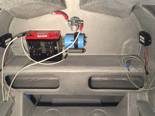
Battery, master switch, ground strip, capacitor, fuse blocs. Just getting started...
|
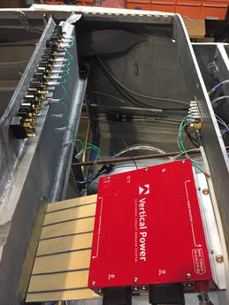
VP-X on a glassed in shelf - I got this shelf idea from Neal Johnson. Ground connections available on F-28 and 6awg lines run from Master switched buss to VP-X and firewall ground to IP ground.
|
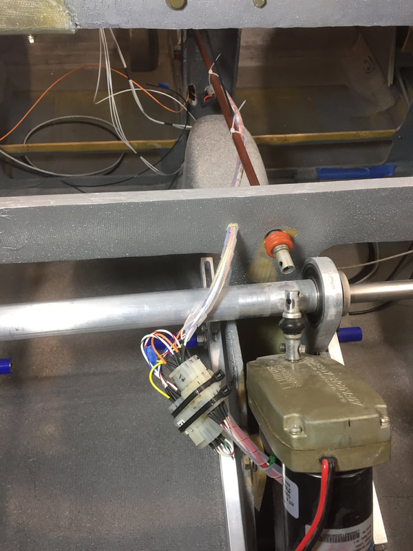
Nosegear Wiring:
|
After 3 years of hand connecting partially completed Molex connectors using the original wiring diagram and a bird's nest of wires, I'm finally ready to cut and organize the wiring and make the connectors with real pins inserted throughout. What put me in a position where I thought I was ready?
|
|
Instrument Panel: see separate page for this
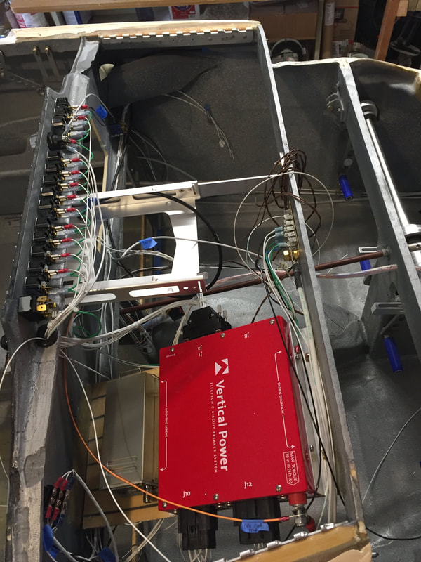
VPX Wiring:
|
Working in this area in late Jan early Feb 2018. Following the VPX install guide and running the configurator to assign circuits and switches to the various internal circuit protection systems. I ordered the "harness" but that just means they send you all the raw materials to make the VPX connectors. You still custom make the harness. I guess the main savings in time was that all the wire I needed to put into the higher power connectors (not D-sub) were taken from pre-crimped wire they provided in the "harness kit". If you don't mind crimping these yourself, and know what wire you want, you can save some $. For me the latter was a just as much a benefit, since I hadn't really documented every single wire size and length. Using their wire sets saved me from having to figure all this out. Here's a quick pic after getting all the connectors made, and running wires to the various places where loads are. You can't easily test the load switching with a voltmeter because there are voltages on the load lines even when they are off (if the VPX is powered up). Read about this. It has to do with solid state nature of the VPX. However, it's easy to make an LED load tester and put it on each circuit and flip the respective switches and make sure everything works as planned. Not difficult.
|
Still a little messy, but it's getting cleaner. Yes it was a real bird's nest when I first put the connectors on the VPX, and I still hadn't started running all the ground wires...
|
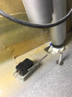
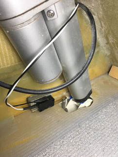
Warning LightsI've got 3 warning lights above the EFIS and one warning light at the fuel pump selection switch. I'll get more information on the implementation of logic for these lights later when I've completed this work, but they rely on sensing various things, so I'll start with some documentation of these sensor installations.
Speed Brake/Landing Brake Micro Switch The first microswitch I installed was the switch near the actuator behind the front seats. It's a simple push type switch and I used the version with a long switch lever arm so I could keep the switch back away from the opening and the actuator. The pole that pushes on this lever arm was made with a threaded stud and a short section of 1/4" Al tubing we use for venting the fuel tanks. I tapped the inside of the tube so it threads onto the stud to get the height right, then bonded the stud to the speed brake flap. I then bonded the actual switch to some left over glass/PVC foam sandwich from armrest construction and marked where it needed to be to switch on when the speed brake is all the way UP. Then drop the brake and bonded it to the seat back support as shown in the figure. |
|