Chapter 21.1 Strakes (Prep through "top hats" for upper skin)
|
|
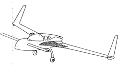
I've been finishing up the whole top-side of the fuselage over many months including Ch 18 and return to Ch 13 for the Nose Top, to get things reasonably well complete before moving to Ch 21. One should realize that I've already completed Ch 19, and I've built the Winglets but will not mount them and make the rudders until I get to hangar (for ease of transport) unless hangar availability becomes an issue ... Right now, it still seems like I have LOTS of work to do, even though this is the last Major structural element I think I need for the Cozy. As you probably already know, I'm working out of the garage, and until now that's meant "my side" of a 2 car garage. In this chapter I must occupy the rest of the garage, much to the disappointment of my wife. I've delayed it as long as I think is practical, and so, here we go...
Mounting the Spar:
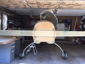
I delayed mounting the Spar until now so I could work on the Cozy in 1/2 of our garage. Obviously with strake installation I must occupy the WHOLE garage and work starts by going back to Ch's 14 and 18 and follow the plans for permanently installing the spar and finishing the connections to firewall. This took a couple of weeks, is documented in pages for those chapters, and subsequent strake work is documented here starting late July 2016.
I delayed mounting the Spar until now so I could work on the Cozy in 1/2 of our garage. Obviously with strake installation I must occupy the WHOLE garage and work starts by going back to Ch's 14 and 18 and follow the plans for permanently installing the spar and finishing the connections to firewall. This took a couple of weeks, is documented in pages for those chapters, and subsequent strake work is documented here starting late July 2016.
Preparations:
Lots of reading and re-reading the plans and how others have approached Strake construction. After turning over several approaches in my mind, I believe I'll use an approach that's perhaps closer to the plans than some have used, but still suited to my available resources with the overall structural intent being paramount. One of the things I'm still trying to figure out is when I'll have to turn the fuselage over. Clearly, by the time I need to apply the UNI skin to the bottom I'll need to be upside down, but I definitely want to minimize how many times I have to do this inversion. When it's time to turn it over, I'll be looking for some friends, as my last son will have left for college :-(
Lots of reading and re-reading the plans and how others have approached Strake construction. After turning over several approaches in my mind, I believe I'll use an approach that's perhaps closer to the plans than some have used, but still suited to my available resources with the overall structural intent being paramount. One of the things I'm still trying to figure out is when I'll have to turn the fuselage over. Clearly, by the time I need to apply the UNI skin to the bottom I'll need to be upside down, but I definitely want to minimize how many times I have to do this inversion. When it's time to turn it over, I'll be looking for some friends, as my last son will have left for college :-(
|
Step 1 - Fabrication of Ribs and Bulkheads:
I started with the normal process of bonding two of the 3/8" H45 PVC foam sheets together on the long edge and 1 BID both sides and peel ply. I'm working with EZPoxy for strakes since most parts will be in contact with the fuel tanks. This was my first large layup with it. I'd done a practice small layups to make sure I understood the mixing proportions (very similar to the MGS that I've been using), viscosity (thicker than MGS) and the cure time with the slow Hardener (maybe slightly faster, but hardly noticeable). I had no trouble with these layups even though EZPoxy/ 87 slow doesn't wet quite as well as MGS. It also has a very strong odor and I wear a full filter mask from the time I open the can to after clean up and make sure the garage door is open for at least the first hour of cure with a fan on. After an hour, I've found the smell dissipates and typically don't need a mask. The other thing to realize is that the hardener is golden brown so the layups are tan colored, vs green with MGS. This is nice as a reminder of where I'm using EZ Poxy for fuel resistance. I then used the layout arrangement published on the Cozy Girls Strakes site, www.cozygirrrl.com/menupage.htm (if you go to this side, click "Chapters" to the left, then select Ch 21 Strakes/your own kit, to find their layout) but modified it slightly to enable me to fit in the 2 long BLE's needed for the extended strakes (the BLE's in the plans and on the layout drawing are not long enough). Triple check your markings before you cut. I found a couple of small mistakes the 2nd time, and this is when I realized I needed to shift the TLE's a little to fit in another long BLE for extended strakes. No problem with the extra lines, I just put little "x's" near the edges where I might be tempted to run the saw as reminder that they were NOT to be cut. When I get some time, I'll draw up the layout I used and put it here. I cut them with help from Garrett (shown) using the Blade Runner (see tips page) which worked fine (1st rough cut to smaller sections of the big sheet, then fine cut on the marking lines). I then used a router to carve out the half circles in the tops and bottoms of B33 and DB pieces. Finally, I put the B33's together and drilled the 1/4" vent line hole per plans. Note that I left the TLE's and BLE's long so I could trim them to fit. I also decided to wait in final shaping of the OD pieces until everything gets set on the spar to best match with the profile of wing and R57. |
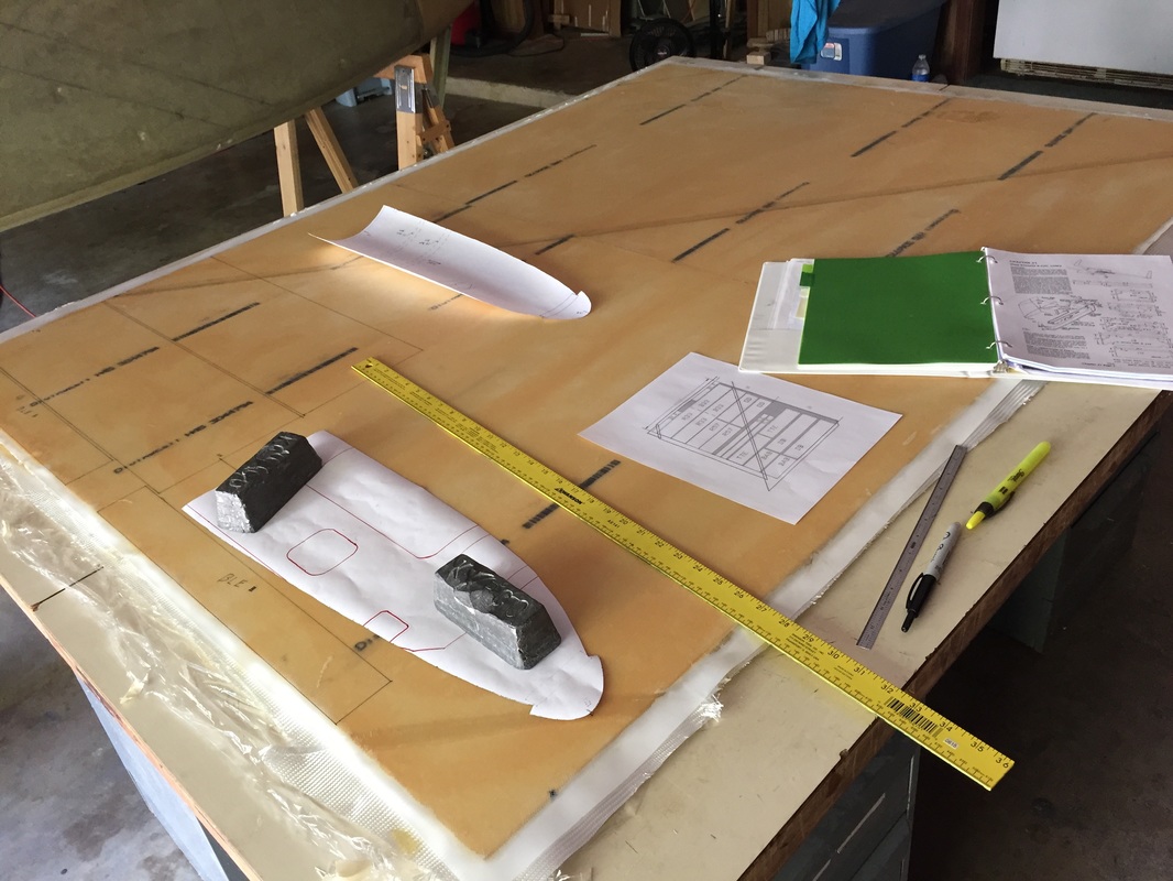
Paper templates for R33 and R57 from Plans/Drawings and measurements for all the rest of the pieces...
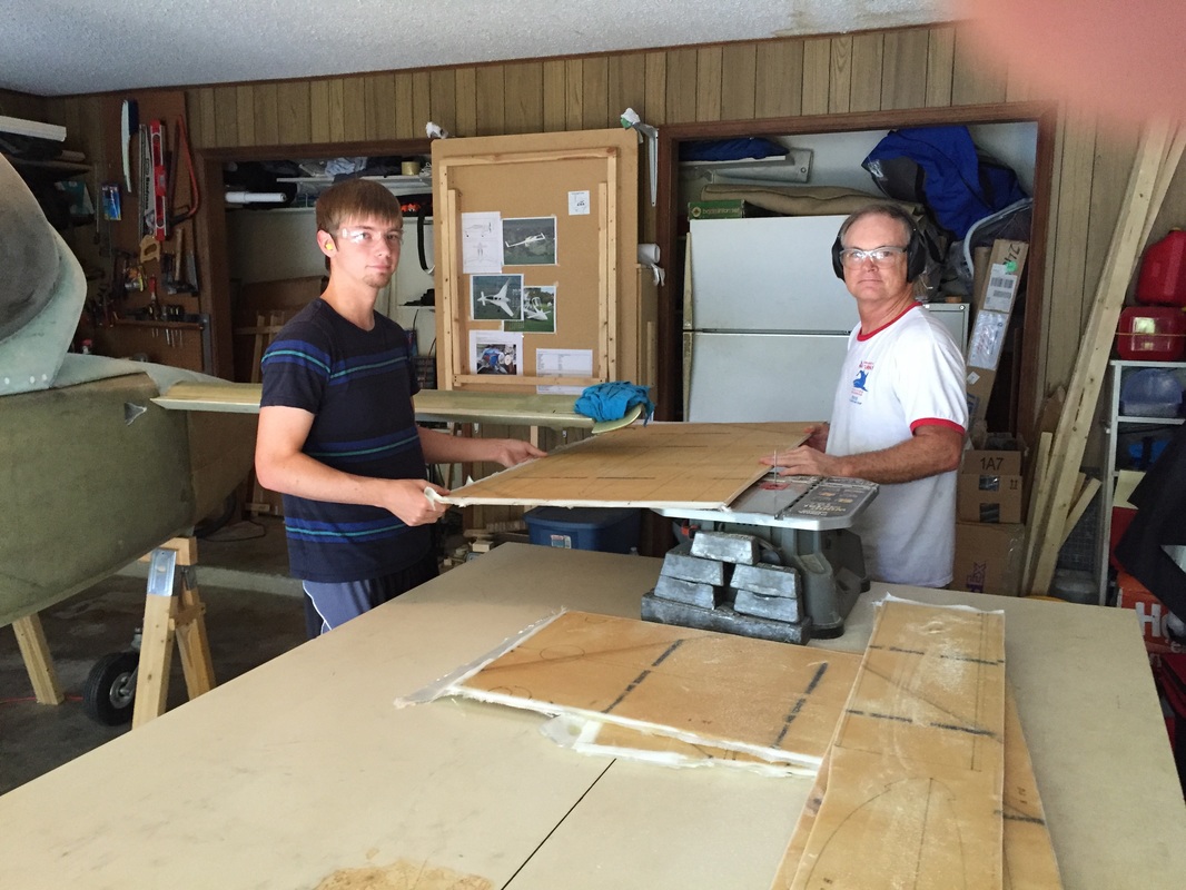
Garrett giving me a critical hand with the sawing of the big sheet down to the subsections.
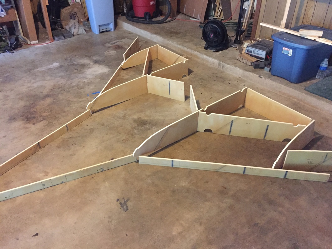
All the pieces after cutout. See notes to left...
|
|
Marking Water Line 17.4 and Body Lines 33 and 57:
Before going further, I need a good WL 17.4 WL and BL 33 and 57. For this I want to use the 17.4 that I used for the wing alignment (marked on the back of the spar). However, when I did comprehensive measurements of longerons, spar and canard I found that my spar and the marked 17.4 WL were about 0.5 degrees off in roll angle from the longerons up near the IP where I had been referencing. After a lot of fretting and measuring and talking with other builders, I knew I needed to use the wings as the reference, since they are the critical aerodynamic surfaces. I would then allow the longerons to be off slightly in roll angle relative to the wings. Likewise important was maintaining wing pitch angles (angle of attack) relative to the longeron pitch angle for the wing and canard and they both measured to within +/- 0.1 degree with the digital level. Good! To confirm everything, I re-mounted the wings on the spar and the canard up forward and checked alignment. I know that the wings twist the spar slightly more now, vs when I have the strakes built, so I will measure this deflection as well. To have room for mounting the wings, I need to push the fuselage part way out of the garage (see picture), and level everything with the 17.4 WL that corresponds to the previous wing alignment. Naturally the day I have helpers available, it's raining (see photo with tent as we wait). OK, rain stopped in the afternoon so Garrett and Reece helped me get both wings bolted on to the spar. Adjustments and measurements using laser level and reference points on the corners of the wings (see Ch 19 wing leveling and plans for displacements from 17.4 WL) went on for a couple of hours as I looked at and thought about what I was reading. Then I figured out what made sense for my Cozy: a) My 17.4 waterline marking on spar from Ch 19 is appropriate and will remain the key reference. I supported the fuselage to get this line level along with zero longeron fore/aft angle (tires have no influence now). With this done, the wing inboard leading edges are right on (within 0.1 inch elevation) 17.4 WL. b) then I took measurements from this plane using the laser at the outboard corners of the wing and the inboard TE, since the plans specify what these offsets should be in Ch 19 (and I used these figures in my water based leveling last year. These measurements looked good, with only a slight dihedral (mentioned in Ch 19 to get good wing root match with the spar). Wing pitch and roll are within 0.1 degrees of plans spec. In my Cozy this flying configuration results in a longeron roll angle of 0.5 degree's down on the right side. I can live with this. With alignment confirmed, I then made spar-end patterns of foam that matched the wing profiles on each side and 5 min epoxied them to the end of the spar to assist with later shape blending the end of the strake to the wing, since I will be storing the wings again later today. With the fuselage still propped for level 17.4 WL, the canard pitch was re-checked using the F template from the plans and showed 0.4 degrees pitch up with respect to the longerons, which are leveled fore/aft with the 17.4 WL. Discussion on the builder's site suggests that this will be good (negative pitch is not good on the canard - as it increases risk of main wing stall prior to canard) Finally, with the main gear off the ground I measured the roll angle of both wheels and the angle between horizontal of the bottom of each tire for later analysis. That latter angle was 0.8 degrees. This may be something I have to deal with later when I have the Cozy in a level hangar by making a slight adjustment to the landing gear. It's not something I can accurately resolve at this stage in my garage. After all this the wings were removed and stored and the fuselage moved back in the garage and propped back up similarly so I could begin strake construction. Postscript from after flying the plane for a year: this slight misalignment of the spar did not have a big influence on the flight characteristics of N78CZ. I tried to align the canard with the wing after finishing the strakes and this may have helped a little but it's not perfect. The result is she still flies very straight with no bad roll tendency. I just adjusted the roll zero ever so slightly to correspond to stable level flight and never notice roll problems. |
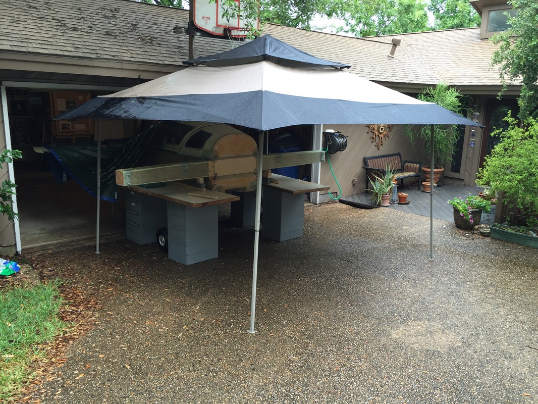
We haven't had rain for weeks. As soon as I need to be out of the garage slightly, thunderstorms come. Same as wing alignment last Thanksgiving...
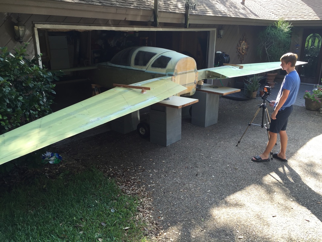
Using the laser to establish flat WL planes with respect to gravity (the laser is on a pendulum)
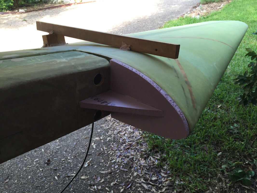
Pink foam based pattern of wing inboard profile to allow match with strake skin later...
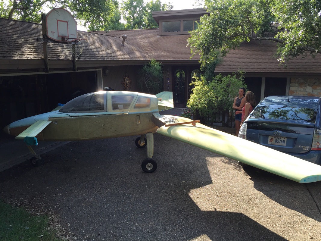
This is everything but the winglets that I've made so far all assembled... Neighbors will stop saying it looks like a boat now!
|
|
Step 2: Assembly of Strake Parts
With the pieces cut out as described in Step 1 I proceeded to flox them in place using the laser to insure perfect alignment with 17.4 WL and angles along the LE. In this initial assembly, I'm only flowing each piece together with EZPoxy/flox and filleting the seams with peel ply finish. The reason I'm doing this even though it's slower than flowing and glassing is that I want to have the whole structure pinned in place (this flox is really strong) before doing all the tape work. Also, some of these corners are quite tight, and getting a good flox fillet is easier for me without the complication of handling the glass at the same time. My hope is that the glassing will be quite easy later with these nice hard fillets already in, and insuring that nothing moves while I press the glass tapes in place. We'll see: it certainly takes longer since I'll have to return to these. Oh, a tip for builders in this section: Don't forget to remove the peel ply! I did relatively wet peel ply for these since I'm going for fuel tank sealing later, and since these pieces are cut from a large sheet that was peel plied as a unit, the peel ply is not easy to see. I use a knife under a corner to carefully get it to start peeling and then remove per normal practice. I just happened to recognize this on the first piece I was working on and realized what a big boo boo this could have been. I pulled all the peel play on these parts immediately after that to insure I didn't get them installed with it still on. Another note: I used an end rib which I cut by using the pattern of the pink foam from the Wing and then offset the cut cline to account for the measured 0.4" thickness of double sided skin layups just like R57/R33 are done. Since I mounted it just inboard of the pink pattern (which is 1/2" thick) I had to shift this pattern forward slightly so that it's leading edge lined up with the leading edge of R33/R57/Pink Pattern. Top Skin and T-Hats: I need to make the top skin and fit it over what I'll call the "strake frame" before I can create the famed "T-hats" for sealing the top fuel tanks, and in fact the whole strake frame to the top skin much later. I started by laying up a pair of H45 PVC foam again just like I did for the frame parts only with BID on one side. Meanwhile, I started making skin templates from poster board paper taped together, so they can bend on the LE curves. |
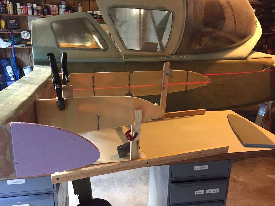
Using laser at 17.4 WL to set height of R33 and R57 (marks from drawings on each)
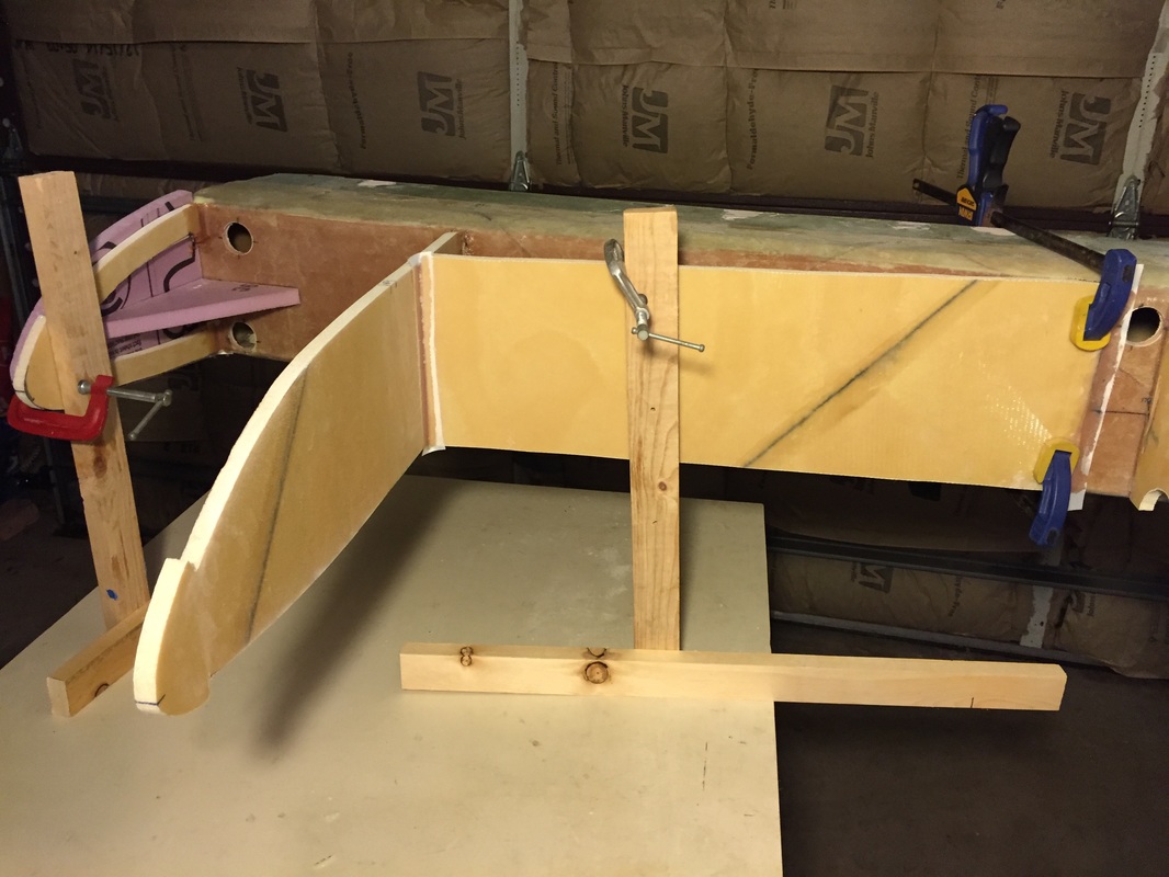
This highlights my jigging technique for the R&B: fuselage and spar are leveled, work bench is not leveled, but it is stable. T-frame is used on bench top to allow adjustable clamping of each R&B piece at correct height and orientation and then they are floxed in place and peel plied. Note I still need to 1 BID tape them later.
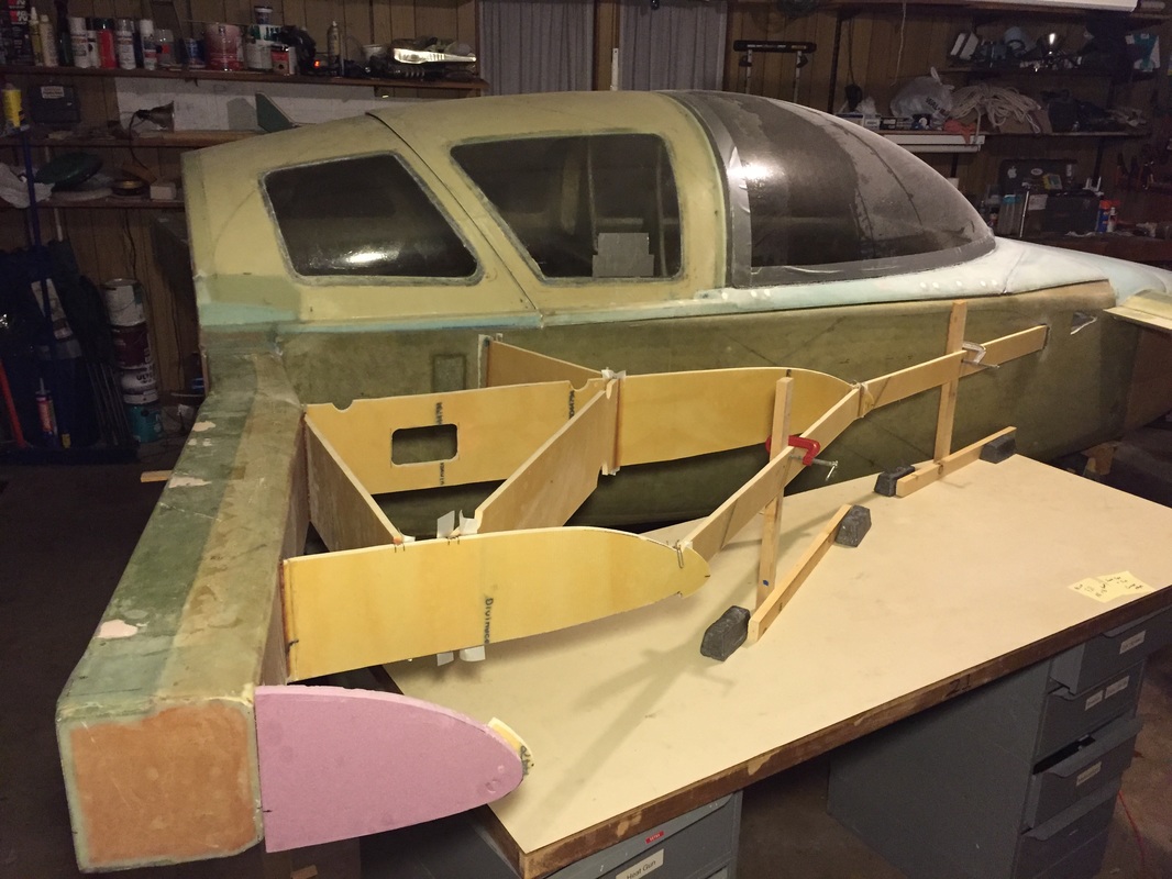
Nearing completion of R&B floxing. You can see my extended strake angle here.
|
|
Top Skin Preparation:
With the ribs and bulkheads/baffles (R&B) floxed on, I could start making the patterns for the top skin pieces. Like the plans, I'm using an inner piece (between fuselage and R33) and an outer piece from R33 to the end rib that I installed to match the pink foam pattern made while the wings were on. I've not started this glassing but I can tell that I don't have enough H45 foam. The ACS catalog for Ch 21 says you need 7 sheets. I used 2 to make all the R&B for both sides, and I can tell now that the skins will take ~2 sheets for each of top and bottom skin on each side. That's a total of 10 sheets (3 more than indicated!) This foam is not cheep, and more importantly it's shipping cost is high because it is so fragile. Too bad I only ordered 2 extra sheets, Damn... Making the paper templates is not a perfect science, and from others' sites you can tell the templates just get you close. I cut the skin slightly big and then refine edge cut it, particularly on the inboard skin that has the curve of the fuselage and the curve of the LE. But first I have to mention that when I cut out the onboard skin for the Right side which I'm working on first, I forgot to turn over the one sided BID/foam layup, or flip the pattern. The result: this skin piece will be the outboard skin of the OTHER side strake... And now I need to do another 2 sheet layup for the other Left side to make the outer top skin for the Right side. Think before you cut... So I went ahead and cut correctly the Right strake inboard upper skin and went through the shaping process. This piece is much more difficult than the outboard upper skin since it has a high sweep angle (Extended Strakes) and I was trying to sustain R33 like airfoil profile near the fuselage. This leading edge near the fuselage has several angles you are trying to satisfy, and you are cutting away some of the flexure of the skin at the fuselage intersection that influences the LE curvature more outboard. I didn't want to crack the BID even with the foam slits so I allowed some profile flattening in the most inboard LE area and got a good fit. I think it looks good and it might get some refinement when I put the foam LE on later. At least it appears that it will be aerodynamically smooth and strong in cruise attitude. I didn't immediately micro the flexed skin, since I needed time to get the other side strake caught up and make a full set of upper skins. So in the interim I inserted tongue depressors in the foam slits to get an idea how the skin would shape at the LE. I used 1/2" slit spacing as others are doing. I also tapered the R33 and R55 in the LE region to allow the skin to fit flat on these ribs in it's flexed configuration. You can see this best in the finished T-hat shapes at the end of this page. |
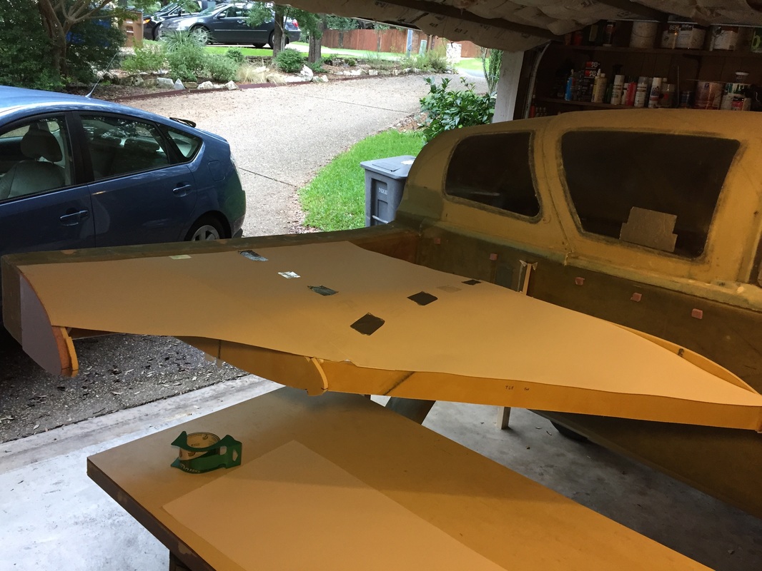
Poster board pattern for outer skin
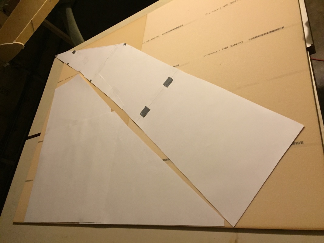
Skin patterns (outer to left) on H45 foam pieces to figure out best way to cut the foam...
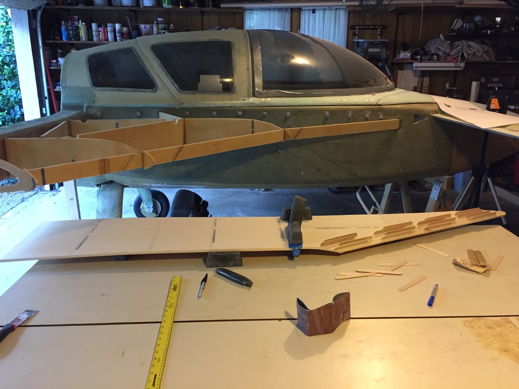
Here's a look at the Right Inboard Upper skin, while I was bonding the flat aft panel to the curved forward panel on the bench. The bond is under the black wights and I'm using Wayne Hick's hinge method. In the background you can see the little pink temporary foam blocks I hot glued to fuselage to support this skin during fitting. Note the wooden stir sticks/tongue depressors inserted in the foam slits to hold curvature in the Leading Edge.
|
|
Final Fitting of the Top Skins:
Before jumping to the T-hats, I'll just make a few comments about fitting the top skins because this required a number of iterations and I didn't see much detail recommendations on it either in the plans or on other builder's sites. I'll describe what I did, which worked well for me. First I need to describe my particular skin design constraints: - I'm using extended strakes so the skin can't be made with one piece (described earlier on this page). This is important because the match line for the inboard and outboard skins I did were on the centerline of R33. (more on this later below) - I'd like to have a smooth transition from the inboard skin to the outboard skin, but that's not really practical with 2D bending of the skins over forms like R33 and R57. I see photos of finished strakes with a crisp crease at this intersection and it looks good. I decided that I would build the skin with the crease because that's what the 2D bending wants to do, and maybe later put a smoother blend in over the top of it. That might be something that I do in the finish stage of building. - I started with the inboard skin and used weights and clamps as shown to hold it in rough position, lining up the LE first. I then marked and sanded the fuselage contact line until it was pretty good match (gaps no more than 1/8"). With this fit, I marked the inboard edge of R33 on the underside of the inboard skin and noted that the thickness of R33 was .4". With the inboard skin removed, I marked a cut line 0.2" outboard of this line and trimmed. That allows this skin to sit right down the middle of R33. - I then did the same thing with the outboard skin: align the LE and mark the underside OUTBOARD edge of R33 on it and mark a cut line 0.2" INBOARD of this line. The result was the inner and outer skins matched each other on R33 and with the LE. Note that you do have to leave a little extra on both the panels where they bend forward at the LE to allow them to taper well and I did this last finishing with a sanding block to make them close together with no gap. - I accepted the profile generated by the bent LE of the inboard skin on the fuselage even though this was a little more shallow than the profile of R33. It looks better and I've seen some strakes get pretty pointy up in this area. Ive still not formed the strake LE foam piece so it can still be appropriate to reduce the chance of flow separation (even though high speed strakes are sometimes designed to promote separation and vortex formation... Not sure enough yet about this for Cozy - will talk to others on this. - Lastly I finished the taper at the spar. For this, I used the actual match points with the spar to set the TE line and the angle of the taper to fit. I cut the sheet at the rear most TE line, and then estimated the taper by eyeballing the spar fit. I then used Dremmel with high speed thin saw to cut just through the glass of this inner skin layer at approximately the taper angle, and then cut the taper with a hack saw blade (using edge of bench as the guide to prevent cutting the foam too much. This rough cut was then block sanded for a nice taper surface. This all went pretty fast, with the main iterations being used on the fuselage intersection line and the R33 LE regions. Note that I built top skins that will go all the way to the wing inboard profile. If for some reason I don't like this in the final installation, I can cut the skin and use shaped foam, but I think it will be stronger and lighter this way. This means I'm using the outboard strake rib instead of the OD frame piece described in the plans. |
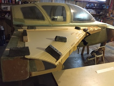
This is a look at how I used weights on R33 and R57, and stir sticks in the foam slits to get the foam to roughly fit the curved profiles. I still needed a clamp right at the intersection at LE and R33 to make that double point connect together
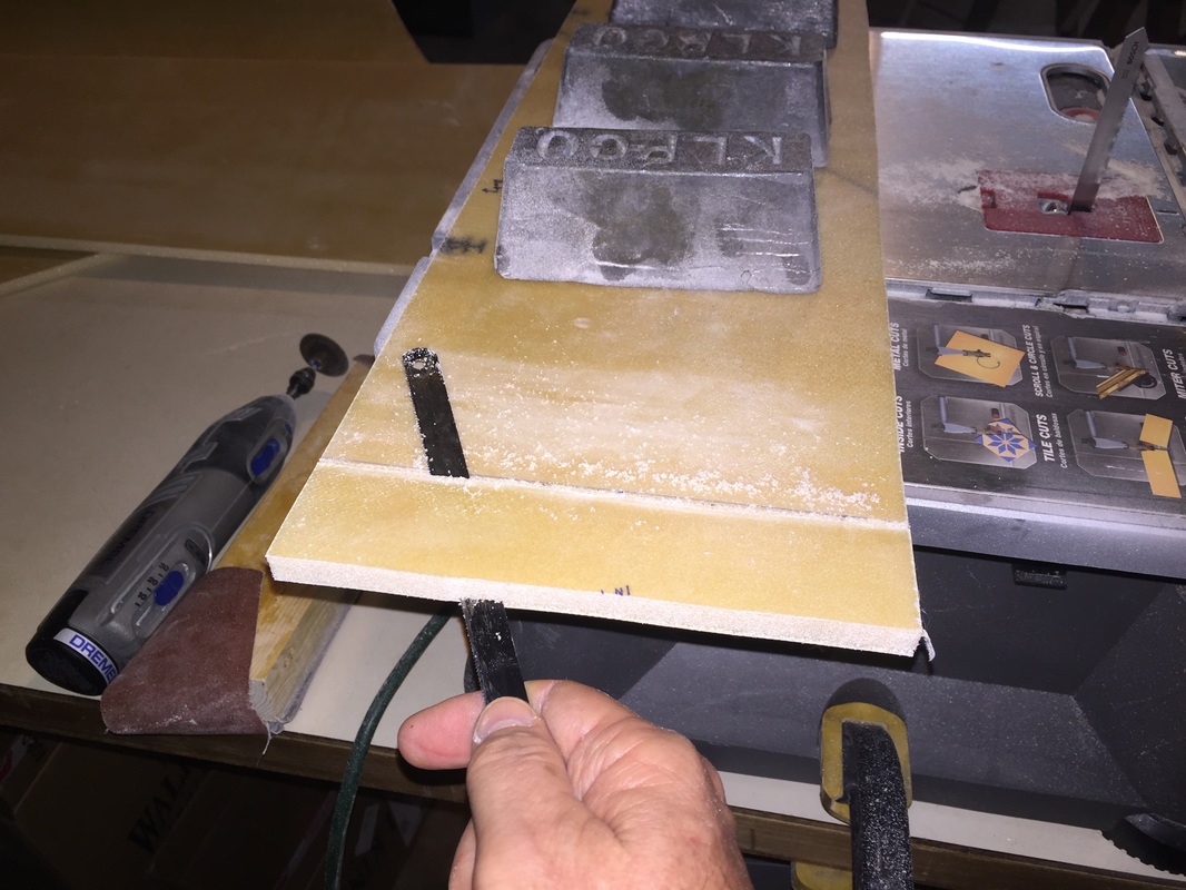
Here's a picture after I cut the TE of the inboard skin that will fit the spar and I'm putting the taper rough cut in with hacksaw blade. (Note from text how I cut the glass first with that dermal to the left in the photo, and in this photo I'm not using the edge of the bench to guide the lower edge of the hacksaw blade as I did later).
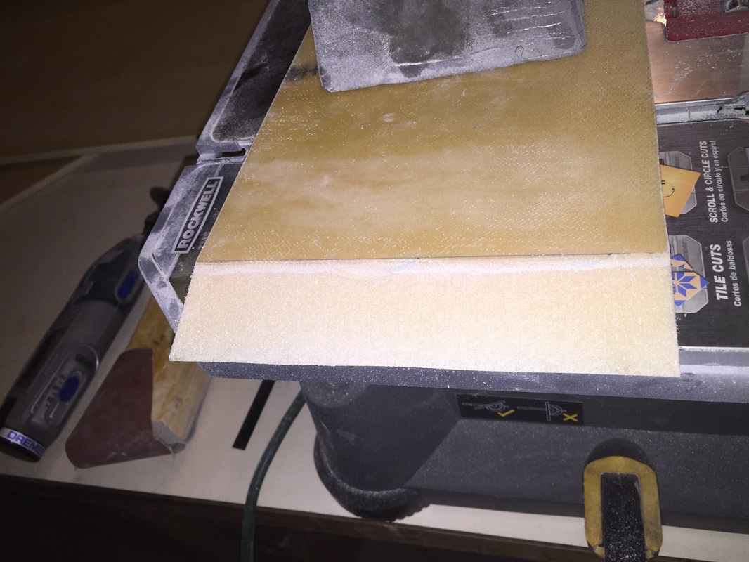
Nice finish taper after I used a sanding block on the hacksawed rough cut...
|
|
Creation of the T-Hats:
Once I had the skins fitted well I was ready to do the T-hat layups. At this point the skins are verified to fit close to the bulkeheads and spar and fuselage, so I just need to flox and tape them on in such a way that the pop off when done... Sounds easy. I was warned by reading other's blogs. This took me an average of 5.5 hrs on each side. Here's what I did: - packing tape the underside of skins where all the bulkheads and spar and fuselage and LE tapes will be. This is critical to get the skin to release after cure of the T-hats. - build up flox ~1/2" high on all the bulkheads/ribs and add a strip of Peel Ply (PP) on top of that (to create rough surface for final bonding of skin at the end of the strakes chapter... - fit the skins back on the way I'd had them before. This squishes down the flox. Note that I didn't want flox or epoxy sweezing up between my inboard and outboard skin panels at R33 so I had one packing tape strip on this line attached to the inboard panel that extended onboard for the outboard panel to adhear to: CAUTION: if you do this, get help putting the outboard panel on to insure that it sets down on this R33 tape line perfectly the first time! It sticks immediately and if not in good position, you might have to remove everything and start over. I was able to get it positioned well each time (Left and Right Strake) but the first time was just luck, and the second time had me really nervous until I was convinced that in fact I'd fit it well. It works perfectly on that seam if you don't mess up this placement. - Then I bent down the LE's of the skins and applied the weights and clamps as shown previously for fitting the skins without the flox - Now the long part: - check all the seams from the underside and if any of them don't have a little flox squeezed for making the fillet, add some flox - then make all the tapes and apply them with finishing surface of PP (I did this by preparing all the materials dry (BID and PP) and wet laying them up on the bench on pallet wrap then transferring the tapes to the seams. This is a lot of crouching and looking up work. Knee pads might help if you use this method. I'm building with EZ Poxy so I'm doing all this with a chemical mask and shop glasses. ALSO remember that where seams overlap, you need to reach under the last layup and pull out the PP from the previous tape so all the PP is on the outside of the tapes. One thing I did in preparation was make a figure with all the seams labeled (green paper in middle of my tape making bench) and pre measured the lengths of the tapes the previous day. Then I could check them off as I made them and not have to take any measurements other than tape length on the bench when doing this job. I let all this cure and then separated the skin. I had to be deliberate in getting the skin to separate. I started on a corner/edge usually the outboard edge and working down the LE and then working back to the inboard TE. Little by little you'll get the epoxy to release from the Packing tape or the packing tape will come off the glass of the underside of the skin. Either is OK. Then pull all the packing tape, PP and trim the tapes to a nice T-Hat. My T-hats are about 1.5" wide after trimming, which is what I wanted. The tapes I used were 2 BID. 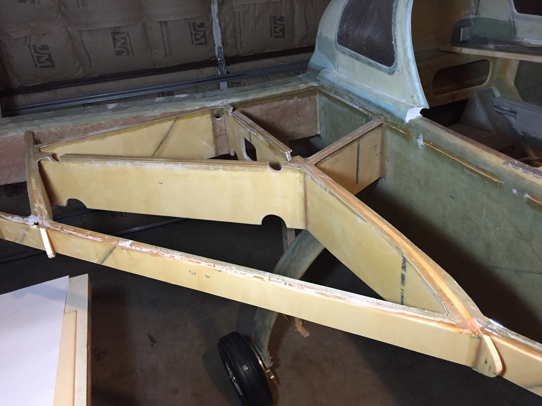
Finished T-Hats. Note the gaps in the tapes on fuselage - I had support blocks in these positions for the inboard skin during the T-Hat construction in theses spots.
|
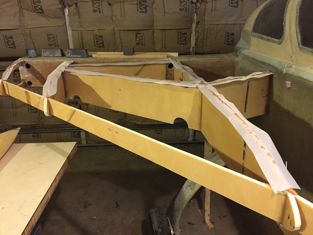
Phase I: flox on bulkheads and PP strip over top. Next set the Packing taped skins on (Inboard skin first)
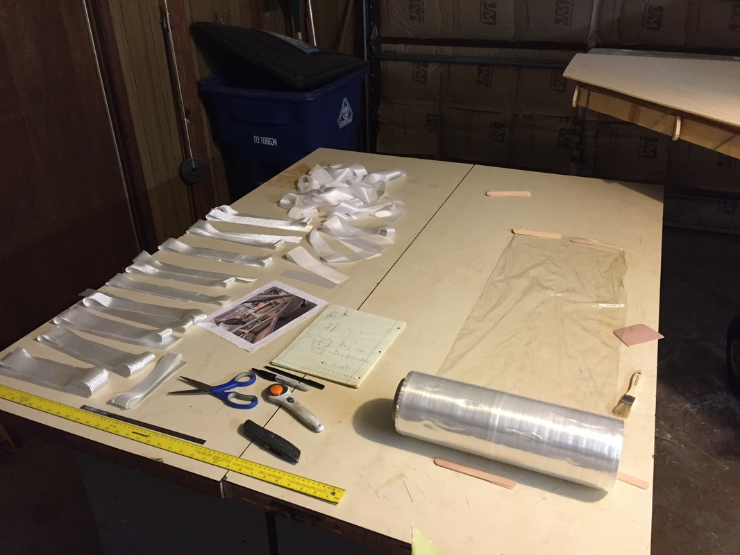
I had this pretty much set up the night before. The taping bench. Pallet wrap prevents sticking to bench, measure and lay PP on top of it, then wet the 2 BID tapes, then cut the strip of pallet wrap with tape on it and take it to the destination seam and lay it in, then remove the pallet wrap layer, and smooth everything in (see not on PP in corners)
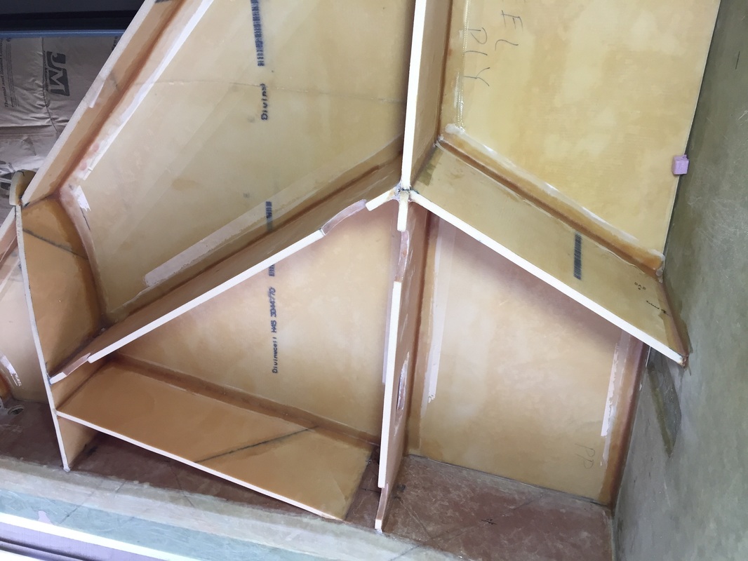
This is what it looked like after 5 hrs of work. 'Resting with my back on the floor for a change, vs crouched under strake looking up...
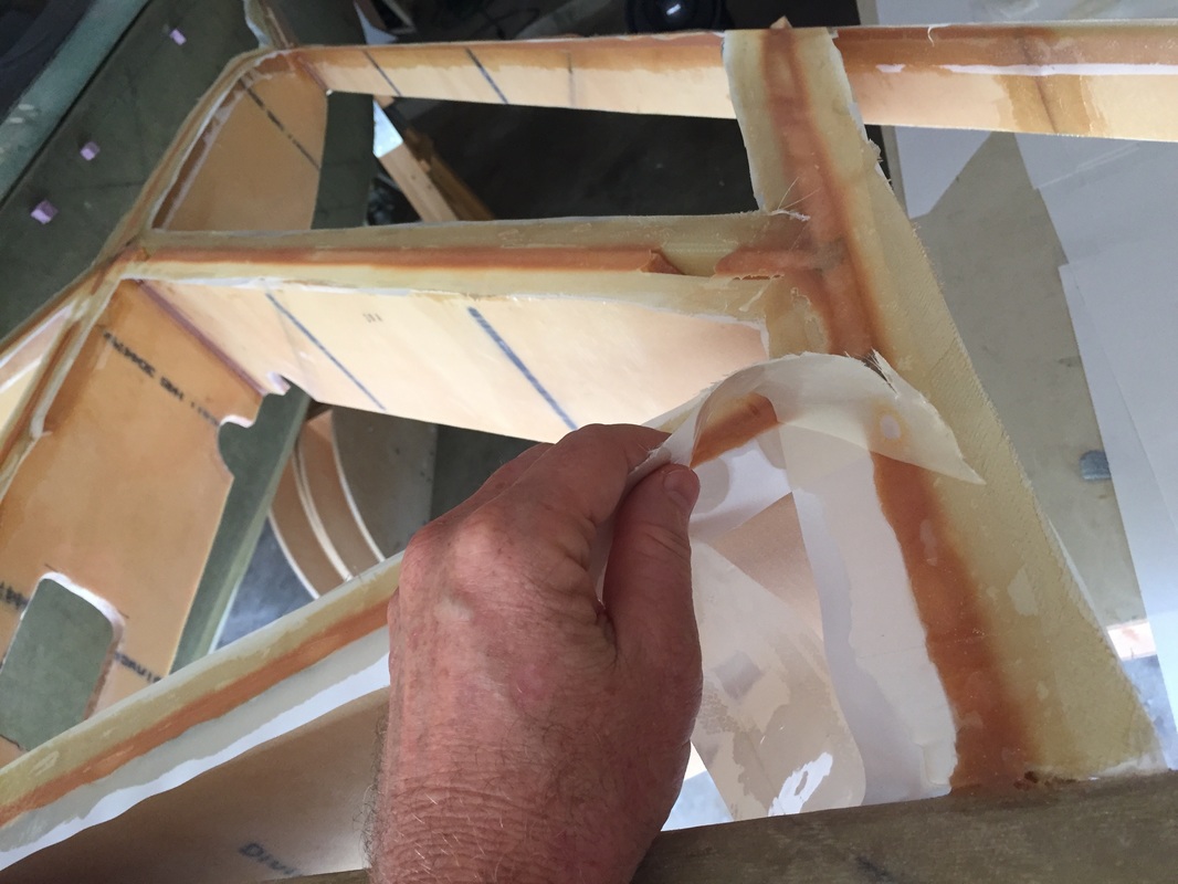
After cure and pealing the top skin off: removing peel ply and any packing tape that stayed on...
|