|
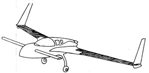
Chapter 19: Wings
|
|
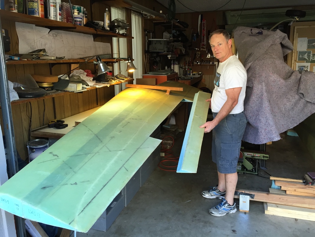
David Pierce built the wings based on Eureka CNC wire cut foam cores to the point that they had the external skin and the internal bulkhead on the inboard ends. I picked up at this point and before continuing to work on wings I wanted to insure I could get them well aligned, so I pushed this up to the beginning of Ch 19. I bought his project in February 2015, and for most of 2015 I worked in Chapters 12, 13, 18 and as appropriate checking work for Chapters 4-11 as documented elsewhere on this site. Since I knew it would be a while before I got to Wing work, I built a cradle for the wings to store them safe and dry under the house with covers to also prevent exposure to even reflected sunlight.
With the experience of work on these previous chapters, familiarity with the plans, and time reading of other's work, I finally felt that I was in a position to continue work on Chapter 19 in the Fall of 2015. Completing the wing alignment attachment to the spar would confirm the quality of the wing and spar construction, and leave me comfortable adding more labor to the wings with confidence that the results would all come together with the kind of performance one expects for a high quality Cozy. This alignment and the Canard Alignment are critical performance governing fits for the aircraft, and are referenced ultimately to the longerons. The following goes through high points of what I did following the plans and incorporating tips as noted from other builders.
With the experience of work on these previous chapters, familiarity with the plans, and time reading of other's work, I finally felt that I was in a position to continue work on Chapter 19 in the Fall of 2015. Completing the wing alignment attachment to the spar would confirm the quality of the wing and spar construction, and leave me comfortable adding more labor to the wings with confidence that the results would all come together with the kind of performance one expects for a high quality Cozy. This alignment and the Canard Alignment are critical performance governing fits for the aircraft, and are referenced ultimately to the longerons. The following goes through high points of what I did following the plans and incorporating tips as noted from other builders.
|
Preparation for Wing Alignment/Attachment to Spar:
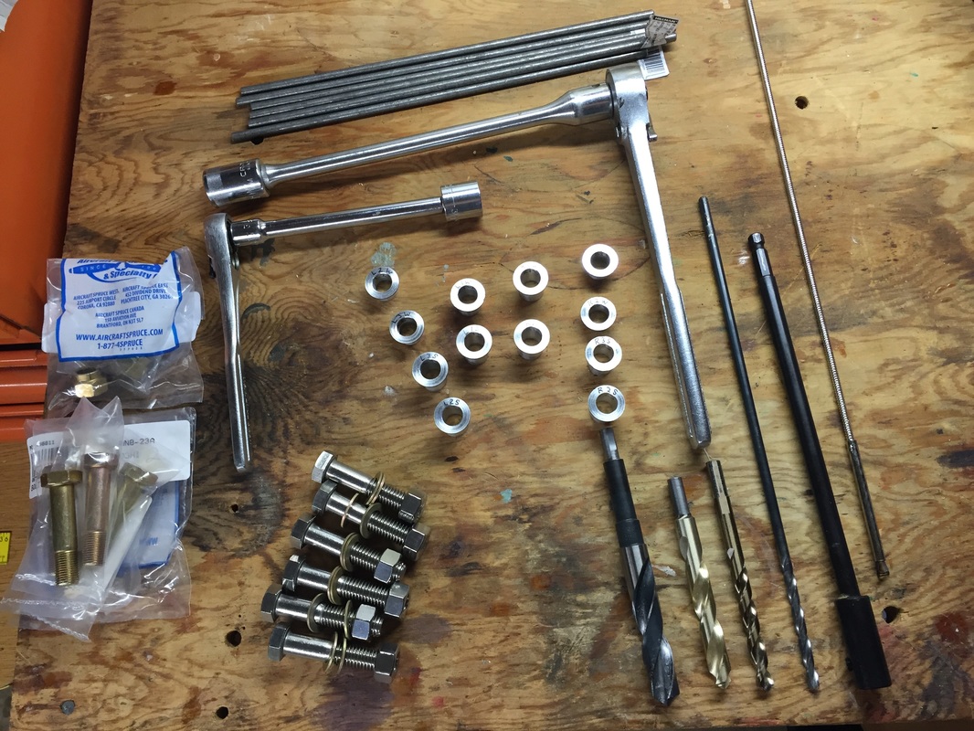
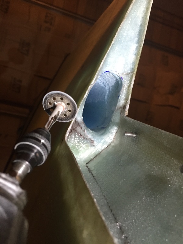
I started by returning to Ch 14 and inspecting the spar according to the plans measurements. Everything checked out well accept the Port side inboard hard point location. This hard point had been glassed in 1/2" to far inboard to have the bushing that will eventually guide the bolt for the wing to be centered in the hard point. I triple checked all the hard points and also their partners on the wings (which are wrapped carefully and stored in a good hanging position under my house) and confirmed that it was just this hard point. I then cut through the flox corner and 3 UNI plies holding it on and was able to get a sharp edge under the aluminum piece and pop it off. I sanded everything flat and roughed the surface in prep for re-floxing without cutting into the UNI plies that were bonded to the spar box because I didn't want to damage any of these layups. I then re floxed the alumni hard point in the correct position (1/2" more outboard from original position) and applied the 3 UNI plies again per plans, as shown in photos to the right. Next I did an alignment of the spar in the fuselage. I positioned the spar firmly between the longerons and found it matched 0.0 degrees in roll with the longerons leveled to 0.0 side to side. In pitch, the left side measurement point on the spar showed 0.0 degrees with the longerons also measuring 0.0 at the forward seat back. On the right side of the spar, I got a 0.6 degree pitch up measurement. Note that the spar top has some layup imperfections which could be causing this discrepancy and as long as I align wings consistent with these measurements, the wings will be aligned with the longerons (the key thing here). So I carefully marked the spar where I positioned the digital level and the readings to be used in correlating with level longerons. These were used for the rest of this alignment process, and again much later (see Ch 14 Step 10) when I actually installed the spar for good. I also inspected the wings and measured the hard point locations and they matched up well to the drawings. Everything looked good, so it was time to get into the plans and make the wing bolt bushings and buy the wing bolt hardware per plans. My friend Danny Jares helped me with some sequencing tips with the lathe in making the bushings and they were a great exercise for improving my skills with this machine since precision and repeatability are important with these 12 parts. Using the micrometer, and properly handling course and fine cuts, as well as using the fine dial gages on the machine became more comfortable after the 2nd and I made a few extras so I could reject those that were not well matched to the spec on OD or flange thickness. I used a 0.505" reamer for the ID which was a great match for the 0.499 OD of the AN wing bolts. All these bushings get reference markings for where they go in the spar and wings once they are cut to match depth of each hard point as I measured through the 1/4" pilot holes (see later). I included a picture below of all the hardware I used in the wing/spar bolting process (with the exception of the 5/8" Bi-Metal Hole Saws that I finally ended up using - Milwaukee brand from Grainger...) I moved the wings and spar out for a practice positioning in my garage (extending out into the driveway) to allow me to mark the ground locations (approximately) where I'll want to have all the water level tubes. It's nice having the extra hands of my son Collin moving these bigger pieces around from cradle to layout and back to cradle with no risk of dinging something... Other preparatory activity was getting a good reference mark on the spar for the 17.4" W.L., which will be used to set up the whole water leveling system later. There is a picture of this reference mark in a picture in the "Taking the Measurements" section below. I also practiced shimming the wings and spar to mark the ground where everything will be and save the shimming materials (each support has a different hight from ground because the ground is not level in the drive way). Next I built the water leveling system following on-line tips from Wayne Hicks and Bernie Siu. A couple of pictures of mine are given to the right (I should have taken another picture when it was completely set up. I set it up several times and still forgot to get a picture. Note that I didn't put a lot of effort into the pink vertical support pieces that hold the clear tubing. I cut them from foam insulation with a knife and twist-tied the tubing to the supports. When doing the measurement, I would straighten the flex tubing and give myself a good view of meniscus and ruler and wing reference point and measure. 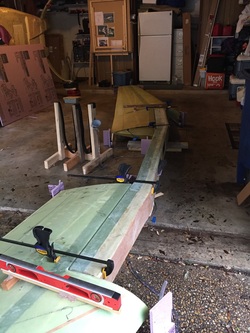
Water Leveling System for Spar and Left Wing (Pink Foam Vertical Supports not yet attached) Using Wing cradle as elevated filler/funnel holder.
|
Original Port Inboard Hardpoint location after cutting off the 3 UNI plies on top of it.
Hardpoint glassed in correct position
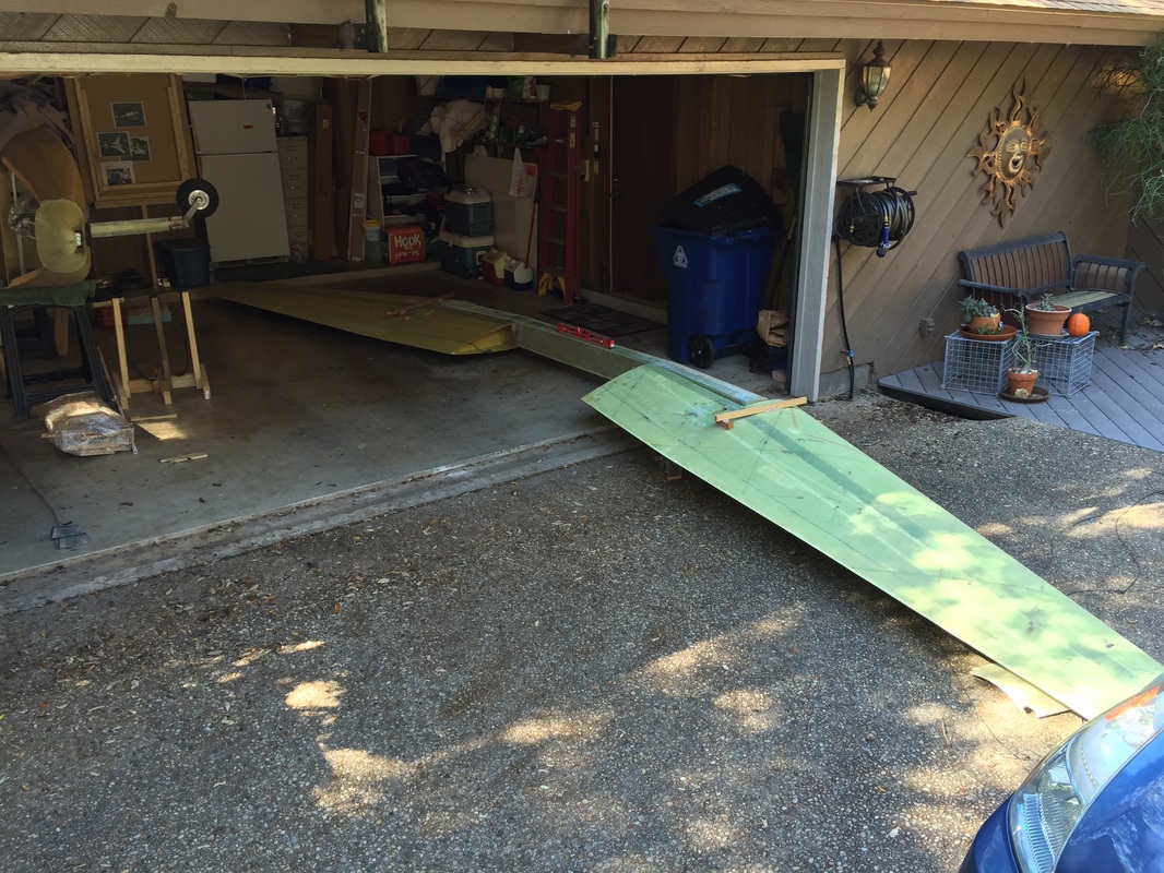
No, this doesn't all fit in my garage! And the ground level is not even in the driveway. Hence need for water leveling system to augment angle measurements.
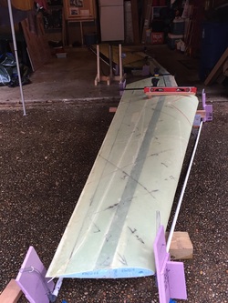
View of Water Level System for Right Wing (Pink foam vertical supports not yet attached)
|
|
Measuring and shimming for Alignment and creating the holes for Wing Bolts and their Bushings:
I moved the wings and spar out for a practice positioning in my garage (extending out into the driveway) to allow me to mark the ground locations (approximately) where I'll want to have all the water level tubes. It's nice having the extra hands of my son Collin moving these bigger pieces around from cradle to layout and back to cradle with no risk of dinging something... Other preparatory activity was getting a good reference mark on the spar for the 17.4" W.L., which will be used to set up the whole water leveling system later. I also practiced shimming the wings and spar to mark the ground where everything will be and save the shimming materials (each support has a different hight from ground because the ground is not level in the drive way). Next I built the water leveling system following on-line tips from Wayne Hicks and Bernie Siu. A couple of pictures of mine are given to the right (I should have taken another picture when it was completely set up. I set it up several times and still forgot to get a picture. Note that I didn't put a lot of effort into the pink vertical support pieces that hold the clear tubing. I cut them from foam insulation with a knife and twist-tied the tubing to the supports. When doing the measurement, I would straighten the flex tubing and give myself a good view of meniscus and ruler and wing reference point and measure. With the leveling system in place I used a measurement plan as shown in the diagram to the right. The water was filled throughout the apparatus for equilibrium hight match at the 17.4" reference points marked on the spar first (1L and 1R). Then height of wing reference points (red dots) were measured relative to the water in tube at each location. This effectively provided several ways to check the wings and spar, and since I had written on the spar the angle measurements they had when mounted in the fuselage, a good idea how they would convey later when everything would integrate on the fuselage (since angle measurements I'm working with are typically less than a degree). The first time I really did a thorough leveling and alignment of the wings and spar, I clamped everything and bondo'd wings to spar and drilled through the hard points with long 1/4" drill. When I tried to open the holes with a 5/8" Carbide Tipped Hole Saw, the teeth were ground down without getting 1/2 way through a single hard point. I queried the builders group and from the responses figured that I was working the saw for too long an increment (maybe 2-3 minutes at a time) AND I didn't realize that Carbide Tipped was not the best for cutting metal. Back to the internet and querying the Builders Group set me up to retry a week later with the following preparation: a) I bought 3 Bi-Metal 5/8" hole saws (much harder and more appropriate to metal use like Aluminum) b) I prepared my 3/8", 1/2", and 5/8" drills to fit into the same extension I'd bought to run the hole saw through the spar (since none of these drills were 10" long like the 1/4" pilot hole drill). When I went back to open the hole with the 3/8" drill bit it was griping the Aluminum and I was having some trouble getting the extension's set screw to hold the bit snuggly given the heavy torque load both in drilling and extraction rotation directions. I decided to give the Bi-Metal hole saw a try and with a pattern of drilling no more than 60 seconds at a time, and alternating between 2 holes at a time, I successfully opened all the holes. YEA! I found that after the 4th hole, a switch to a new hole saw was good for keeping the cutting rate up. Both hole saws are still useable though, and the 3rd that I'd bought I kept in reserve. I checked the saw temperature often with my finger to insure I wasn't pushing too hard for too long on any individual hole. If I could keep my finger on the saw, then I figured it was not too hot, and assumed a similar temperature for the aluminum hard points. That being said, this opening of the holes still required patience. Lots of clearing of the slugs each time you penetrated a layer of glass or aluminum, and blowing out aluminum filings and letting things cool meant it took about 3.5 hrs to get everything cut. Others may be faster or slower, but that's what it took me. The holes came out very good and the bushings fit very well. This was a bit more of an ordeal because the first 5/8" hole saws I had were not Bi-Metal, and I was working out of a too small garage, so I had to take everything apart to secure the garage. Otherwise this is a doable job (Alignment, boring out, flowing and Bolting) in 1 day IF: you have the bushings the right length or can cut them quickly, and you allow for cure time after this full day of work. I'm sure there are pro's out there who are faster, but this was my experience. |
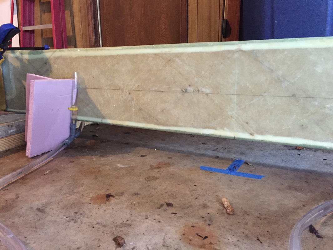
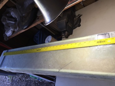
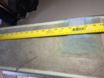
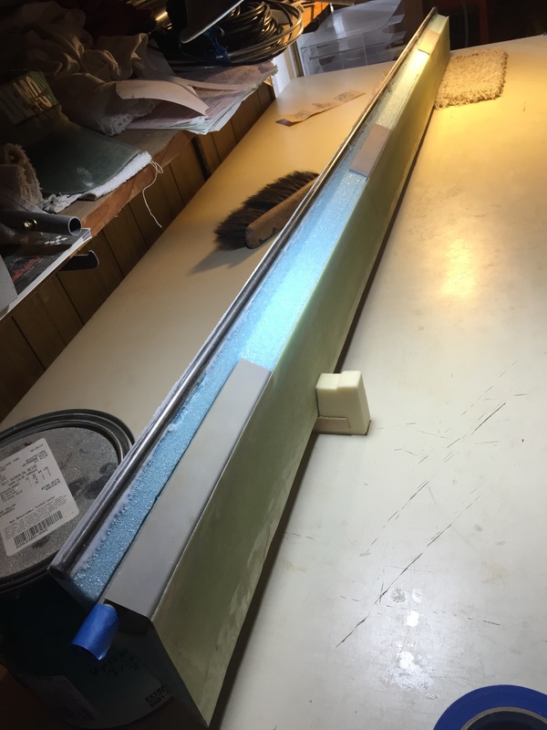
Spar Back face with 17.4" Waterline Marked and one 1L reference tube filled to this mark. Now ready to read wing corner heights above this water line reference.
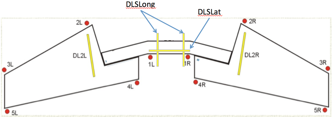
Measurement Diagram for Leveling Wings: (Derivative of Bernie Siu's Diagram) Water level measured at red dots. Water level referenced to 17.4"WL marked from 1L to 1R on Spar rear face. Digital Level measured at yellow lines. DLS = Spar measurement, DL2 = Wing Level boards
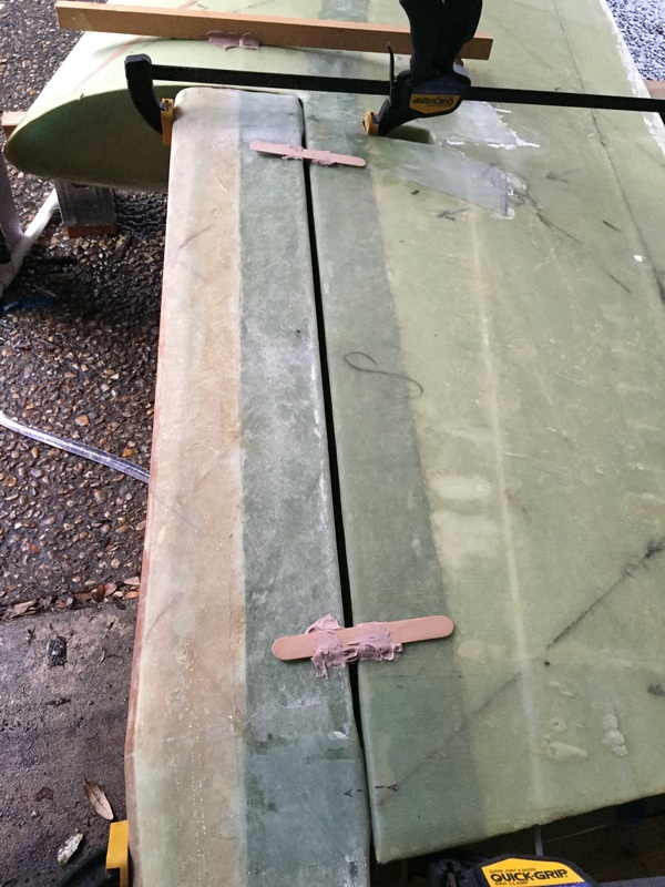
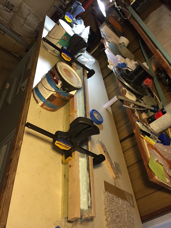
Bondo-ing the spar/wing interface with everything clamped once you have Alignment: to get ready to drill through the hard points (starting with long 1/4" drill)
|
|
Floxing and Finishing the Alignment:
To finish the alignment: flox the bushings, install the waxed wing bolts from the wing side and then gently work the wing/spar together again. This alignment, and in particular the bolting, really requires another person to help you. My youngest son, Reece, helped tremendously with this process. Other tools to keep on hand: - Flashlight for looking into spar when sticking extension into previous hole - magnet on a stick (for getting things that drop in the spar when you don't want them to. Also used this to put the washer on the bolt before putting the nut on - remember, you are doing this from a small hole ~6" from the bolt inside the spar). - Digital level (essential for this task) You really need to be patient. Leave plenty of time for the alignment. As others have stated, you will be measuring and shimming a lot. I would get measurements good and then leave it for 30-45 minutes and come back and check it. A stable measurement is what you need when you will be bondo'ing the system and drilling it. Take your time. I had to compromise on right wing dihedral to get the inboard upper wing skin to match well with the spar top edge. This required the right wing tip to be an inch higher than specification, while retaining proper incidence angle, and translates to ~.6 degree's of dihedral - not a problem as documented in the plans. The left wing required no adjustment of this type, but a washer was used in the upper outboard bushing-to-bushing interface to get the incidence angle perfect with all the bolts snugged down. I'm very happy with how this came out and it's an indication of the quality of work David Pierce and his wife did in the wing and spar builds. |
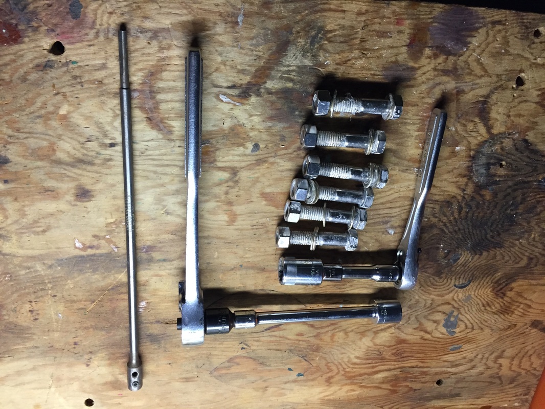
Waxed Stainless Steel surrogate wing bolts with associate ratchets used for installation/removal. Not the shorter one goes on the wing side and should fit in the "pocket"
|
|
Side Note for those working in confined spaces:
Because I'm building in a garage and this setup is much longer than my garage, I had to do it with the garage open. This meant that I had to take everything apart and store it after the initial 1/4" pilot holes were drilled while I re-grouped to finish the 5/8" holes. While I had the wings and spar separated, I measured the hard point depths as recommended in the plans with only the 1/4" holes. With these measurements, I prepared the bushing lengths custom to each hard point as recommended and was ready to install them immediately when I had the 5/8" holes cut. When I realized that I was going to have to set everything up and align again after having the 1/4" pilot holes through all the hard points after the first alignment, I cut 6 1/4" steel rods of 12" length to use as alignment pins when re-assembling the wings to the spar using the pilot holes. This worked great, and saved me lots of time in alignment the second time around (along with preserving the shim stack for the various areas (wing and spar). If you have to do something similar to the above and may have to deal with inclement weather (ask me how I know) it's also good to have both a tarp to cover the wing (with weights to hold it down in the wind) and a large enough pop-up style tent to cover if it rains (again, ask me how I know). |
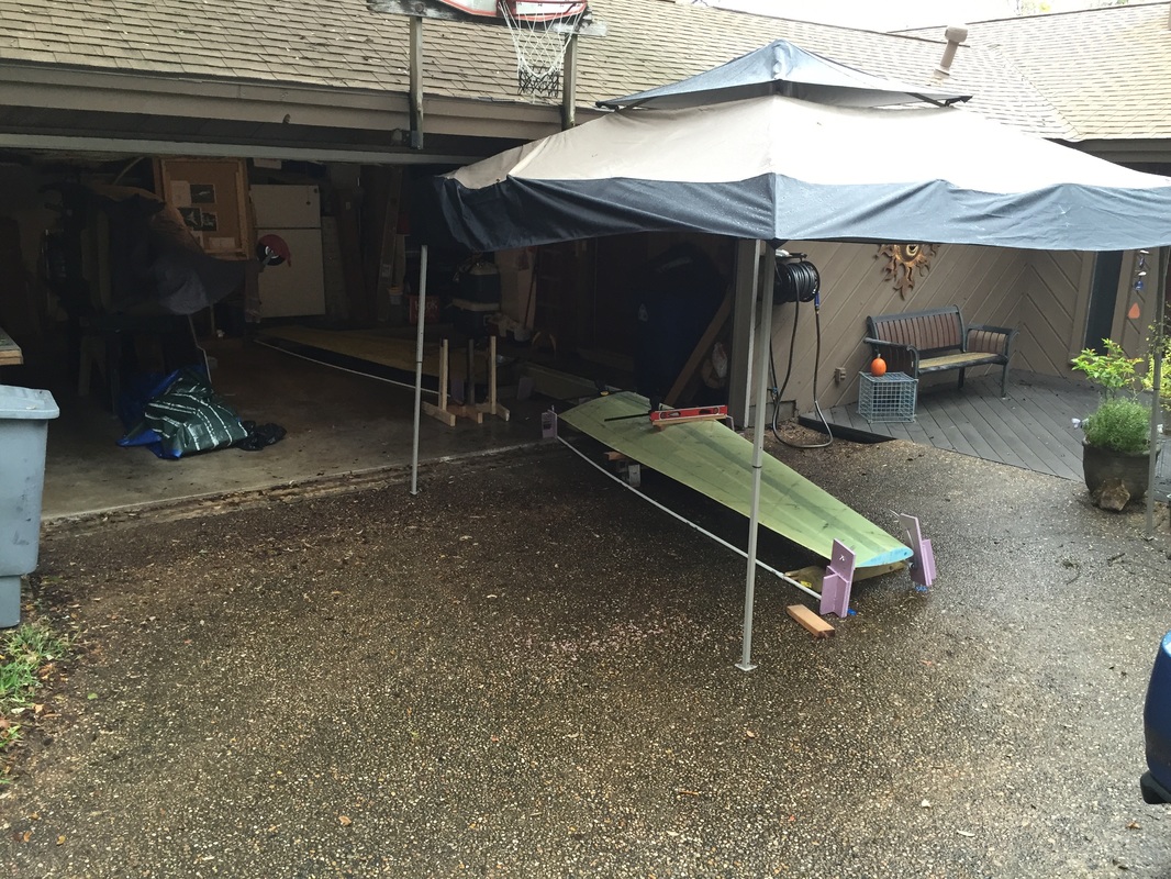
Pop-up Tent I used to protect wing and me when measuring and aligning in the rain. Yes it does rain occasionally in Austin (after several years of drought)
|
|
Ailerons
I was a little nervous starting this section after reading the plans and archives and watching the builder's group conversations suggesting that building the ailerons were one of the more difficult parts of the Cozy Project. I believe this difficulty stems from the combination of: - High standards for layup quality and component positioning to meet the balance standards (see the hinge balance test later). - Low clearances in general for the moving components to keep them aerodynamically clean - Layup in confined spaces (in the aileron pockets) - Layup over complex and very long thin shape (over the leading edge of the aileron - Maintaining accurate hinge alignment - Doing a "blind" bond of the hinge to the aileron prior to riveting At the time that I'm doing this update, I've gotten through one aileron mounting, and am much more comfortable with the techniques involved. I followed the plans and took Wayne Hicks' advice on using an Aluminum angle to help me with the 3 hinge alignments, and things have worked out quite well, if not absolutely perfect. I'll cover the high points below where I had some difficulties, and note where I did something that seemed particularly helpful if it didn't seem to be so important to me in the plans at the time that I read them... First, cut the ailerons out of the wings. Because I hadn't built the wing base structure (David Pierce built these wings), it was an act of faith when I used the dremel with small/thin abrasive wheel to cut into it according to the plans. As noted by others: read carefully and measure and double check before you cut. Some of the key measurements are made along the foam core bond lines, not perpendicular to the trailing edge TE (but you are cutting perpendicular to this TE). Use a square to check the top skin and bottom skin lines are perpendicular before you cut (a mistake I made on the first wing cut, from going just on accurate measurements to the plans). Even with this small error, my ailerons swing free, but it could have been a little better. LATER UPDATE: long after I finished the ailerons, Joe Polenek generated some great step-by-step directions for accurate cutout of the ailerons. Mark Zeitlin published them in the Ch 19 section of his CAD files page here: CH 19 cutting directions. Glassing the aileron pockets in the wings: the main thing I'd convey here is how hard it was removing the strip of peel ply that was left under the foam for bonding to the inside of the wing skin. You first get the foam out as noted in the plans, but the peel ply can get under some of the foam that you want to keep. I read from others that they back filled the foam with pour foam after it got torn out with peel ply removal. I didn't have that much foam torn out but my first finger and thumb were quite sore from the extraction process. I tried using other tools and certainly used a razor blade and at times a sharp putty knife to help me get a portion of peel ply started, but they would eventually cut the peel ply when I wanted to maintain a grip and keep the strip coming off. Be patient. The peel ply has to come out to get the bond you want with the skin. I found that my finger and thumb, once I got a little corner on it were the most effective at judging how much and at what angle I could peel this material off with minimized breaking (and subsequently starting over. Another little trick I used in one section that worked was grabbing the peel ply perpendicular to it's tape line with a pair of needle nosed pliers, and then rolling the peel ply like a jelly roll onto the pliers for 4-5 rotations. Then I'd get a new grip with the pliers and keep going. The actual glassing of the pocket went really easy. I wetted out the 3 ply BID on the bench on a layer of saran wrap/pallet wrap and then had Collin to help me carry it over and lay it in the pocket (it's too long to handle with one person). All my angles were smooth inside and I used only light micro on the remaining foam and got a great bond with about 1/2" of extra BID sticking beyond the wing cut line. I'd say it's a must to have the wing jigged TE up for this (all of the aileron work after the cut out above). I then glassed the inboard and outboard triangular pocket sections as specified in plans and the extra ply at the A2/A5 Bracket locations. Preparing and laying up the ailerons. There are several steps here for getting the balance weight and A2 and A5 brackets and A10 tube into the foam. Just follow the plans. I used the Dremel with the same thin abrasive wheel mentioned above to slice a slot under the skin for the A2/A5 brackets to be micro'd into. The difficulty I had with the the first aileron I did was getting the single BID to wrap well onto the external skin (both top and bottom). I had the aileron jigged leading edge up as required, and had pre wetted the layup similar to what I'd done with the pocket layup with a backing of pallet wrap to allow me to handle it wet when laying it over the aileron. I must not have had enough rounding both up around the counter balance bar and down around the A2/A5 bracket edge because I just could not get the BID to stay down on the skin. This was exacerbated by having a little bit of the pallet wrap (which extended about 1/2" to 3/4" behind the edges of the wet BID) tucking under the BID and getting between it and the skin. By the time I realized this was happening it was too sticky to fix without destroying the BID and getting epoxy further down the skin (bad for balance). So my solution was to get a couple of the 1/2"x1" wooden strips that are used by ACS in supporting foam shipments and clamp these strips down on top of the BID/skin interface to try and hold the BID in place. It worked OK, but I had to go back after cure and pull the bad pallet wrap out where it had tucked under (typically 1/8" to 1/4"). I also found after cure that I should have used more clamps along the length because there was unequal pressure even with the boards... The result was fixable by trimming away excess overlap BID that didn't adhere well. Using a needle/syringe to inject epoxy under some of the areas where there was not good bonding (this was easily visible) and clamping them better. All this took a few days of inspection, thinking, sanding, injecting, curing, inspecting, and sanding more to get the result of having at least a 1" BID overlap bonded well and flush with the outer skins. I resolved to try something different on the other aileron, and I'll document that when I get to it soon. For now, I wanted to move on and install this one and see if there were any more surprises... Getting the hinges in and aligned was really straightforward following the method Wayne Hicks published on his site using a very straight Al angle extrusion as the hinge alignment reference. I clamped all the hinges to this Al angle (the side that bonds to the aileron), lining up their hinges by looking at where the corner of the angle met the cut-outs for clamped side of the hinge. This assembly could then be positioned on the wing (with the .2" hinge recessions made per Fig 49, and added clamps to the wing at the other side of the hinges so that it looks like Fig 51. The whole Al angle rotated great with all hinges perfectly aligned to each other and sitting in their right position on the wing. Then I just marked the wing and match drilled through the upper skin and the hinge plates. Unclamp everything and bolt the hinges to the wing (mark all the hinges so they go right back where they were when match drilled). I used 10-32 anchor bolts for this and standard 10-32 nuts at this stage (not lock nuts) so I could snug them down and still easily get them off later. Bonding the aileron to the hinges: I again followed a tip from Wayne Hicks and used the hack saw blades in the hinge slots to maintain pressure on the A2/A5 Brackets with the hinge once the aileron was positioned the way I liked it. I'd pre floxed both the face of the hinge (using masking tape to keep epoxy out of the rotating part) and the mating areas on the aileron brackets. I waited 32 hrs before checking to see how it came out (typical cure time for checking my work with MGS 287 at the 65-70 degree temps in my garage this time of year is 24 hrs). Removed the clamps and it rotated perfectly through full range of motion. Awesome! I'm really impressed with the plans for this aircraft and the great tips I got in this area. Now on to the other one... 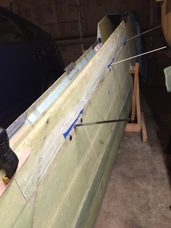
Right aileron during bonding to hinge: clamps holding alignment with wing at Trailing Edge, and hack saw blades stuck in hinge slots (Thanks Wayne...) NOTE Left Wing with hinges awaiting it's turn just behind...
Will continue here... last updated 1/20/16
Discuss the vacuum method used on other Aileron... |
Relief... Sawing into a good wing layup tests your nerve.
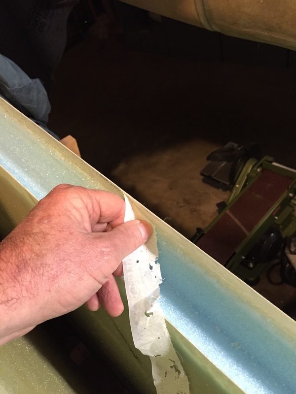
Making finger/thumb sore pulling peel ply in confined space (this is a nice big piece - the little ones are a bear!)
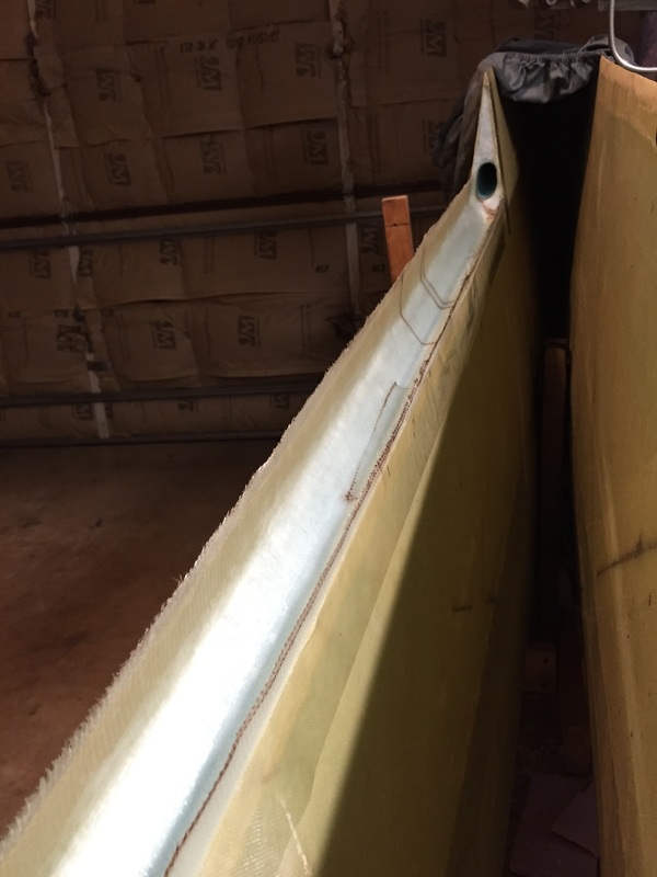
Glassed the aileron pocket. Note the glass comes up past the upper and lower skins and must be knife trimmed or ground back later.
Left aileron jigged up and ready to micro and glass per plans Fig 50.
My clamps on aileron glassing step. I don't recommend this method yet, because I had some difficulties with it. When I get the other aileron done I'll have a stronger opinion on best way. Paint buckets prevent aileron from tipping over (even though it's jigged) because of the clamp weight.
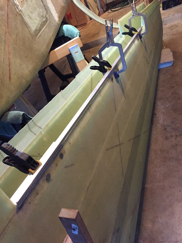
Al angle used to align the three hinges. Each hinge is clamped with the black clamp to the angle. The wide vice grips reach over this assembly and clamp the wing side of the hinges to the inside skin in their proper location. With all clamped in place the Al angle should rotate free (just like the aileron will). Match drill the wing/hinge plates at this point and bolt them in place, Then you are ready to remove the Al angle and replace it with the aileron!
|
|
Finishing out the Ailerons:
Need text here (end bulkhead glassing, |
|
|
Aileron Controls:
Need text here (torque tube fitting, and providing appropriate bolt clearance, bracket installations, spherical bearing, clearance and reinforcement glassing in the wing inboard bulkhead, connecting up the linkage, and testing) All done and needs documentation from the log. The YouTube video below is an initial test of the full linkage in the wing for the ailerons. You can't see it in the video, but the aileron is moving based on this finger input. Both aileron linkages have been tested. The spherical bearing is not tightened down or glassed in, as it's probably going to be replaced with a more high quality (and more expensive!) one later. |
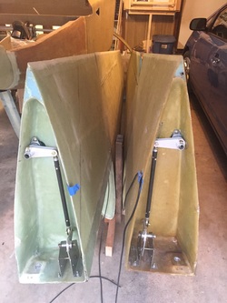
Both aileron linkage sets are completed through the wing inboard ends. Everything still needs to be tightened down, but that will happen after wings are on spar, on fuselage... and after fireproofing foil has been attached.
|