Chapter 28.1: More Improvements
This is an extension to Post Phase I Improvements and describes additional projects I'm working on or completed to make N78CZ the full Cozy I want.
|
Heated Pitot Tube:
I have a standard pitot tube in the nose and with an eye to eventual IFR use, I'm beginning to look at having a heated pitot. All of the ones I see pre-built are angled tubes on a projected blade bracket and I want to keep my location in the nose. I've seen some work by others designing and building their own with Cessna pitot heaters. I've started designing my own with an emphasis on really simple operation, and utilization of my solid state VP-X electrical system. I've bench tested the temperature controller and heaters on a surrogate pitot tube: .6" dia Al round bar, and it's working as expected. I set the temperature I want and the controller turns on/off the resistive heaters to hold this temp within 2 degrees F. I bench tested all this with a battery first and using a round aluminum bar for pitot tube substitute. I then tested with the controller interfaced through the VP-X and re-purposed the Cabin Lights switch and circuit. Finally after I'd switched the heater pads and temperature probe I tested again before final install of the fully configured pitot tube in the nose. When ON, the heater pads and controller draw 1.2A (verified in the Skyview/VP-X display and 0.0A when no heating is needed (the controller draws <100mA when it's passively monitoring). Slide show to the right gives some views during the installation process. |
|
Strake Windows:
Ever since I saw Marc Zeitlin's fuselage side windows, I've wanted some way to increase visibility down from the fwd cockpit. I decided early in the build that I wanted to implement extended strakes and planned to figure out a way to cut windows in them. I left this as a task until after Phase 1 and before final paint because it was not critical to getting the plane completed and like many things that I wasn't completely sure how I wanted to do, I thought I'd learn from flying, and then do the mod with that knowledge. The final implementation did include making the pilot side window openable so I could reach the canopy latch, which would enable me to latch the canopy and lock the plane from the outside if I ever decide to trade the weight of the canopy lift actuator for a passive lift. Here are pictures illustrating what I did. I really like the results. If you look further down on this page to the Checklist Pockets section, you'll see what they look like after all the masking is removed.
Ever since I saw Marc Zeitlin's fuselage side windows, I've wanted some way to increase visibility down from the fwd cockpit. I decided early in the build that I wanted to implement extended strakes and planned to figure out a way to cut windows in them. I left this as a task until after Phase 1 and before final paint because it was not critical to getting the plane completed and like many things that I wasn't completely sure how I wanted to do, I thought I'd learn from flying, and then do the mod with that knowledge. The final implementation did include making the pilot side window openable so I could reach the canopy latch, which would enable me to latch the canopy and lock the plane from the outside if I ever decide to trade the weight of the canopy lift actuator for a passive lift. Here are pictures illustrating what I did. I really like the results. If you look further down on this page to the Checklist Pockets section, you'll see what they look like after all the masking is removed.
|
Co-Pilot Side Window Buildup
|
Pilot Side Window/Door Buildup
|
|
Upholstery:
I've been flying my Cozy for over a year with just high density foam for seat cushions. They are extremely comfortable and I've asked around locally to see if I could get someone to put nice covers on them, and was frustrated that most upholsterers didn't want the job or bid $1000 per seat to do it. We're in Covid time, so face to face conversations were difficult to arrange, and I suspect that there was a disconnect between me and them on what I really wanted: simple, clean, and inexpensive. So I finally just decided to make the covers myself. If after a few years I want something fancier/more expensive, I'll upgrade. Essentially I'm making custom shaped slip covers for the foam that I've already cut to the shapes I want. The foam is 3" thick high density mattress foam which is firm and provides great support. I'm 5'9" and I want my eyes as high in the cockpit as possible while still allowing good neck swivel without hitting the canopy. I have excellent runway view in landing, and generally a more open feel for the cockpit anyway. I tapered the seat foam to zero thickness at the leg openings in the Instrument panel, because it makes getting in/out easier and extending feet beyond the pedals is easier as well. I also have a movable 2" thick wedge that can be used to boost up or provide some additional lumbar support depending on my passenger's preferences. For really tall passengers I'll pull the covered 3" foam back panel and have them use a 2" softer foam that I've used before and my few 6' passengers have preferred. Headrests were made with the same softer 2" foam. All are covered with Navy Blue Duck Canvas I bought on Amazon for <$15/yd and it took less than 5 yards to do front and back seats. |
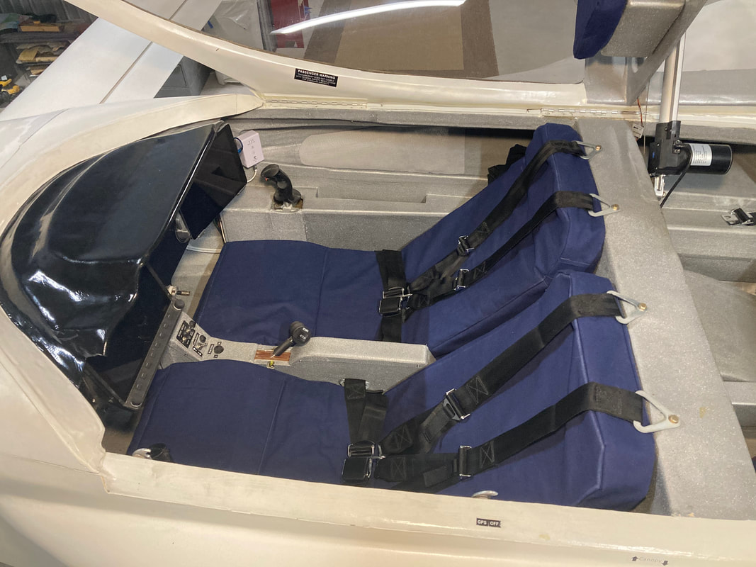
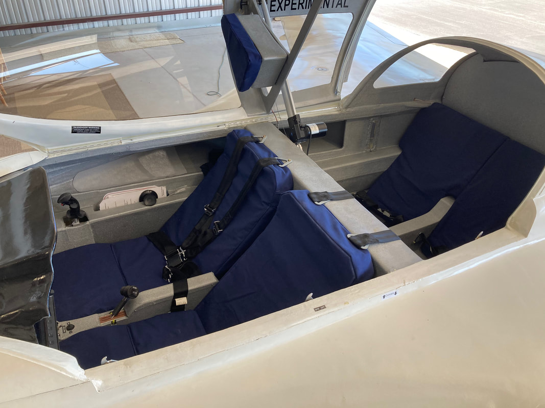
|
|
Belly NACA Scoop Improvement:
As a part of continuing to look at ways to reduce drag, I returned to the NACA's with the idea of implementing corner fences recommended by Klaus Savier. Before doing anything I tufted just behind the corners of the upper and lower NACA inlets to see if I could see a problem with corner bleeding turbulence. What I found, was that there was no bleeding in the upper NACA's all the way to top speed in level flight (~184kts TAS) but the lower NACA is completely separated behind the lip all across. Not good. Note that I'd removed the extra scooping lip from Phase I testing, because it wasn't making a difference in oil temps and was certainly causing more drag. After some thought and careful examination of the NACA as mine currently exists, I theorized several potential problems: a) the flow through the oil cooler is pressure limited already, more inlet area is not helping and is just creating more drag b) when I made the NACA more narrow laterally a long time ago, it resulted in about 10" of length that is not not spreading per normal NACA design. I believe now that this parallel side section is ruining the NACA efficiency by not continuing to grow the vortices on each side that pull air into the inlet. I believe the result is weaker flow induction by the time the inlet lip is encountered, which in combination with a lower pressure differential (due to the oil cooler flow resistance) is making it too easy for flow that had developed in the forward section of the NACA to spill over the lip rather than be pulled into the cooler duct. My approach to getting more flow into the duct is to bring the inlet scoop forward to the point where the NACA sides have just stopped spreading, so that it retains NACA side and depth design all the way to the scoop lip. The somewhat smaller inlet depth and associated cross sectional area. My hypothesis is that a smaller inlet area that's ACTUALLY capturing the vortices will be more effective than the larger inlet further aft that's NOT capturing the vortices. |
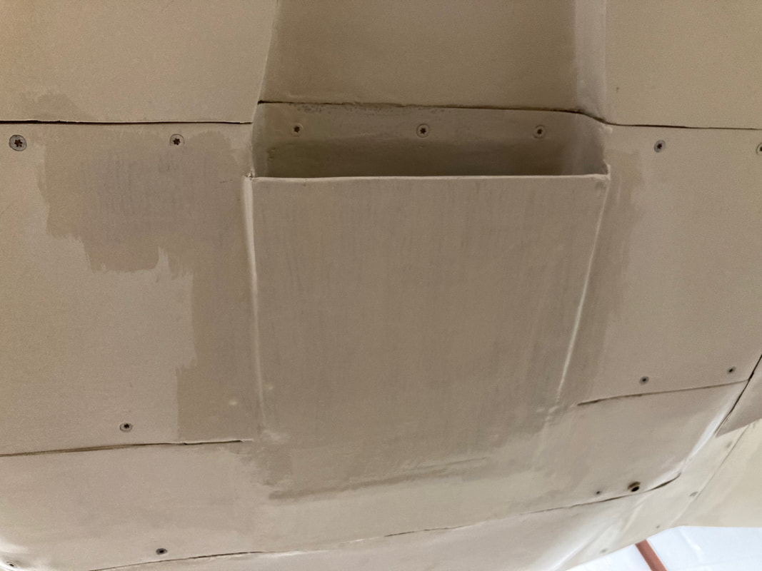
Not a great picture, but best I have at the moment. The scoop lip is 1/4" lower than the bottom of the fuselage, to preserve inlet sectional area with the thin airfoil lip stiffener. The outer skin of the scoop is blended back to fuselage bottom over the length of the main gear cover. I glassed the seam between the gear cover and the back fuselage bottom to keep this smooth and airtight. When I need to remove the cover, I'll just cut that 1BID seam and re-glass it when re-installing.
The initial performance I'm seeing is very encouraging with oil temps at full throttle staying below 205F with an outside air temp of 65F. In June I'm seeing 235F oil temperatures at full throttle operation at OAT of 90F. So far, I'm feeling good about this oil cooling improvement.
|
Autopilot In-Flight Tuning:
I installed the autopilot servo's while waiting to get my Airworthiness Inspection, and discussion on the installation is covered back in my website Ch 26.2 about 1/2 the way down the page. It's all integrated with Dynon Skyview so once you have the servo's installed and calibrated you can supposedly start using them. Well true, but they still need some in-flight tuning to set up well for YOUR plane. I didn't bother with this until I was through Phase I because I manually flew all my test hours and it wasn't until I started XC work that I began to really want to have this capability fully functional. At first I used the Simple Mode of the Autopilot where you set the plane up on the track and altitude you want and have the autopilot HOLD this for you. It's pretty good, but I found the pitch axis needed work if there was any turbulence at all. The pitch axis is not super stable in my Cozy. I could manually trim the plane well, but they autopilot with the default settings could not hold an altitude well. After querying our Builder's Group, a LongEZ pilot forwarded settings that had been painstakingly developed using Dynon's In-Flight Tuning Flow Charts and some trial and error. We weren't sure how well they would work but I found them really quite helpful. I'll probably still tweak them slightly for my plane, but they were a MUCH better starting point than the factory default tuning parameters. If you are in this phase of flying and have a Dynon SV based Autopilot, contact another canard flyer with similar equipment and see what they are using.
I installed the autopilot servo's while waiting to get my Airworthiness Inspection, and discussion on the installation is covered back in my website Ch 26.2 about 1/2 the way down the page. It's all integrated with Dynon Skyview so once you have the servo's installed and calibrated you can supposedly start using them. Well true, but they still need some in-flight tuning to set up well for YOUR plane. I didn't bother with this until I was through Phase I because I manually flew all my test hours and it wasn't until I started XC work that I began to really want to have this capability fully functional. At first I used the Simple Mode of the Autopilot where you set the plane up on the track and altitude you want and have the autopilot HOLD this for you. It's pretty good, but I found the pitch axis needed work if there was any turbulence at all. The pitch axis is not super stable in my Cozy. I could manually trim the plane well, but they autopilot with the default settings could not hold an altitude well. After querying our Builder's Group, a LongEZ pilot forwarded settings that had been painstakingly developed using Dynon's In-Flight Tuning Flow Charts and some trial and error. We weren't sure how well they would work but I found them really quite helpful. I'll probably still tweak them slightly for my plane, but they were a MUCH better starting point than the factory default tuning parameters. If you are in this phase of flying and have a Dynon SV based Autopilot, contact another canard flyer with similar equipment and see what they are using.
Nose Region:
This involves the following improvements:
- sharpening the originally blunt nose tip now that pitot tube heat has been installed. This involved a general fairing around the front of the nose and for symmetry involved reducing the size of the landing light window, and adjusting the landing light bracket to position the LED as low as possible in my particular nose area.
- closing gaps and general fairing of the nosegear door area
This involves the following improvements:
- sharpening the originally blunt nose tip now that pitot tube heat has been installed. This involved a general fairing around the front of the nose and for symmetry involved reducing the size of the landing light window, and adjusting the landing light bracket to position the LED as low as possible in my particular nose area.
- closing gaps and general fairing of the nosegear door area
Canard/Elevators:
- filleting the fuselage/canard intersections. I've seen this on a few canards and the fillets are not large, so they weigh very little and are intended to reduce intersection drag
- I'm also interested in a way to adaptively fair the outboard elevator counterweight in the high speed condition where I'm flying solo. In this solo condition I find that I need to hold about 5-7 degree's of up elevator in level flight at ~5000 ft DA, but I don't want a permanent fairing here, as it's only needed when I'm solo and flying pretty light and fast.
- filleting the fuselage/canard intersections. I've seen this on a few canards and the fillets are not large, so they weigh very little and are intended to reduce intersection drag
- I'm also interested in a way to adaptively fair the outboard elevator counterweight in the high speed condition where I'm flying solo. In this solo condition I find that I need to hold about 5-7 degree's of up elevator in level flight at ~5000 ft DA, but I don't want a permanent fairing here, as it's only needed when I'm solo and flying pretty light and fast.
|
Strake Sump Blisters:
I have an adequate lead-in fairing for my sump blisters but I hadn't yet blended the aft end of the sump into the firewall profile. I wanted these to be very lightweight, so I used urethane foam strips, temporarily micro'd to the fuselage and shaped with sandpaper to the 3D profile desired, then covered them and the fuselage with packing tape, so nothing would stick, and laid up 2 UNI at 45 bias to each other layers, (also sandwiched in clear pallet wrap) to this. It's nice because the pallet wrap clings to the packing tape and I only had to put pressure on the aft edge to insure it tapered flat to the fuselage near the firewall. Once the epoxy cures, I pulled the shell of glass off, then removed all the foam and micro, and floxed the shell back in place. At this point I needed pressure on the upper and lower flange near the sump blister, and again on the aft edge to insure it was in good position. Then micro the outside, sand, and primer. I'm still in the sand and prime phases and will post pictures when this is done. The resulting pieces are super light (I should have weighed them) and the shape is much more appealing. |
|
Canopy Fit:
Over several years since finalizing the canopy glassing and fitting, my canopy has distorted slightly. This is despite putting a small rib inboard of the aft edge, where others have noted this problem. The mis fit is the canopy is slightly high on the centerline forward, and on the sides aft for the canopy. I addressed this with slight fairing fwd on the IP cover, and trimming/glassing/fairing the aft canopy fairing areas.
Over several years since finalizing the canopy glassing and fitting, my canopy has distorted slightly. This is despite putting a small rib inboard of the aft edge, where others have noted this problem. The mis fit is the canopy is slightly high on the centerline forward, and on the sides aft for the canopy. I addressed this with slight fairing fwd on the IP cover, and trimming/glassing/fairing the aft canopy fairing areas.
|
Upper Cowling:
I worked on improving the lower cowling previously as part of getting the oil cooling and exhaust system improved. I was fortunate to have great help with in flight photographer Jack Fleetwood early in Phase I to record yarn tuft separations. Now I'm focused on the upper cowling, and essentially this involves reducing the size of the aft opening between the upper and lower cowling, without creating separation. This will provide better inflow to the prop and increase overall efficiency. The first enabler here was reducing the size of the cooling plenums for the aft cylinders (#1,2). I was confident doing this now, after lots of time in Phase 1 tailoring the cooling flow to all the cylinders. With this process somewhat complete, aftmost cylinders #1&2 run a little on the cool side. After flight testing these lower profile plenum aft sections to insure cooling performance was still great, I began looking at how I could cut the upper cowling from the aft edge and pull the upper panel down, and some of the side panels inboard, to reduce drag without creating separation. After a couple of months of marking and thinking about it, I bit the bullet and grabbed the multitool to cut. To the right is the progression in pictures for the modification. |
|
|
Mirror to Read Pilot Side Fuel Sight Gage:
Got the idea from seeing a mirror in Lacee Lamphere's Cozy at the Co-Pilot side sight gage so when you looked at it you could also see the one on the other side. I'd been using a small hand-held mirror to look at the Pilot side gage and decided to just mount it on the Co-Pilot headrest, which isn't that far from where I was holding it previously. The advantage is that it got the mirror out of CP arm rest pocket so it wasn't in the way of passengers. It's on a little ball joint, so it can be adjusted for accurate viewing |
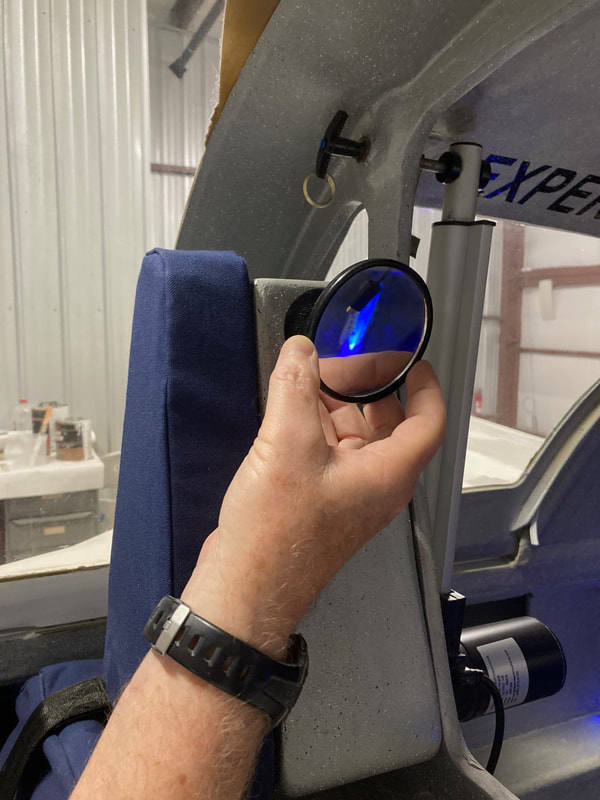
Adjustable mirror looking at fuel sight gage behind me (with blue LED lighting)
|
|
Fairing Key Areas of the External Plane:
I've been flying this Cozy for a little over 18 months now, and this period has included a number of improvements as documented here that didn't change the already very good flying qualities of N78CZ. As noted many times, I'd not painted this plane during the build because I wanted to insure it didn't need exterior adjustments before that commitment and expense. I'm now starting to see the light at the end of that tunnel. With this in mind, I've started the process of sanding and smoothing the exterior surface/primer in preparation for paint. This is the work most of us don't get much pleasure from as it's physical sanding, pinhole filling, low spot identification and filling and deciding when to stop... I still believe that waiting until now to do this fine smoothing and painting was the right approach for me for a few reasons:
As this progresses, I'll get some updates and pictures here. |
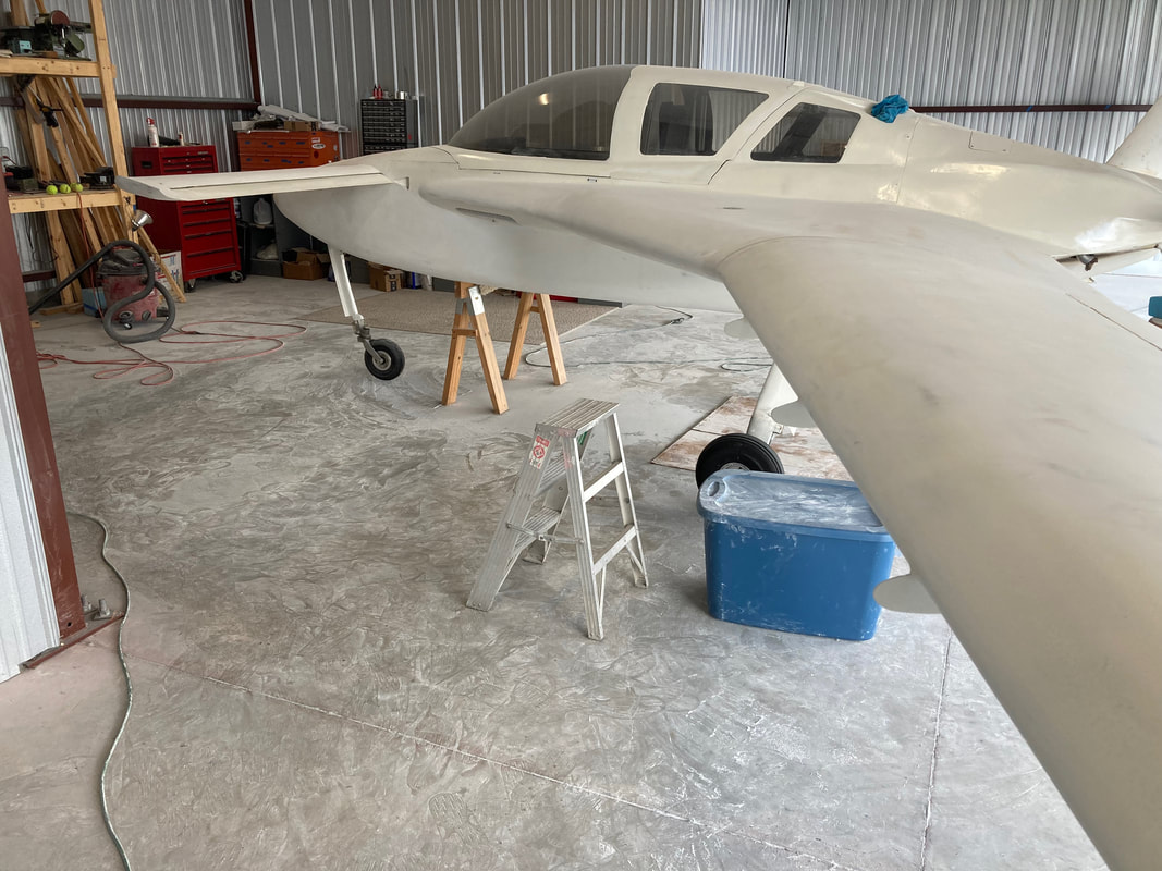
This is just part of the dust I'm generating preparing the primer for paint...
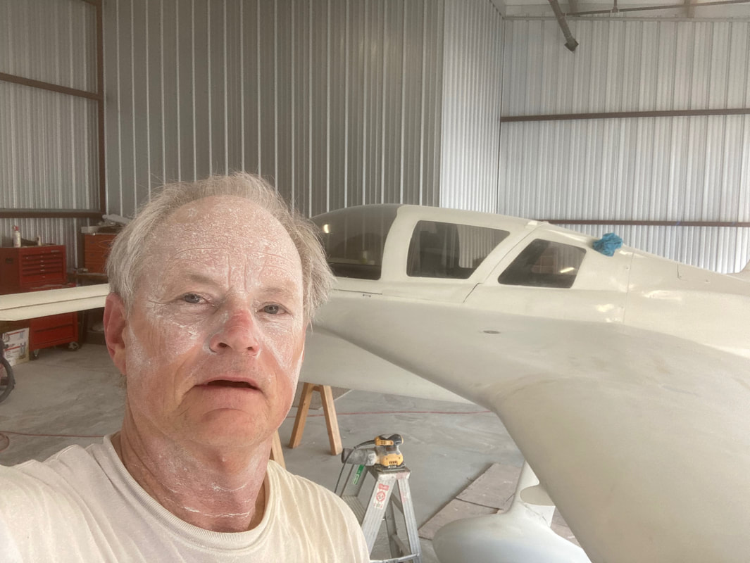
Wearing glasses, Nose/Mouth Respirator, and Over-Ear Hearing protection, you still get caked working under the wings and fuselage. And it's 90 degree's. Loosing weight every day.
|
|
Painting:
At some point most people in this process one has to decide when you've spent enough time smoothing and you have to paint it and move on. My tolerance is for sure lower than others because I've seen a lot of smoother planes than mine. However, I'm still happy having transitioned to the paint phase and chose to continue with Southern Polyurethanes products after being quite happy with their epoxy primer. I watched YouTube videos of car painting and bought a better paint gun than the inexpensive one I used for primer and set up to go with Base White and Universal Clear coatings for my Cozy. I also decided to design in some dark blue "pincer stripes along the upper and lower corners of the fuselage to provide a little bit of identity, and added some matching features on the canard tips and upper winglet tips. With these areas painted first (rattle can) they got masked off for the white base coat over the whole plane. I worked first on the wheel fairings, cowlings, and nose hatch covers since they could be removed easily and painted in a corner of the hanger to get a feel for the handling of the base coat and clear. This was helpful, since I had some drips, that could be fixed, but I still had difficulty in a few spots on the plane. Nevertheless, I got it all done over a few days, with most of the time going to preparing the hangar and masking to contain overspray and the resulting dry powder that lingers when you spray. Obviously you need good PPE/Respirator for this work! When I get time, I'll post a few pictures here of the final result and also update a picture on the Welcome page. It's a 30+ ft paint job, but I'm finding a way to live with it. Not easy considering I spend much more time closer to it than 30 ft... |
|
|
2nd Try With Clear Coat:
So I lived with the above blemishes for several months while I've been working on getting the plane IFR Certified and me through the Written IFR exam, and just enjoying flying it. In the process I tried different methods of cutting and polishing with compound and polish but it only worked well in one or two areas, and was not a solution for most of the topside problem areas. I then shifted to using 400 Grit (and 220 on some drips) to re-smooth and prepare to put another coat of clear on just the areas where it was particularly not nice and glossy. The other thing I'd noticed was that even areas of the wing tops that were pretty good, there were dust spikes that you could not see but feel with your hands. This was a clear indication that the hangar was just not clean enough for doing this kind of work. So for the 2nd try at this I built a "tent" over the plane in the hanger to prevent or at least reduce the dust problem. The results were much better but I still had some drips and I had one spot that despite some 400 grit sanding and use of wax remover, I'd not been aggressive enough in getting every bit of wax off (because the clear orange peeled just in this area). What this showed me however, was that I was getting better with setting up the gun and most importantly gaging the coating as I was putting it on. This is really difficult in the hangar under the tent because great lighting really helps. You want to put a wet coat on, but not so wet that it runs. This depends on the slope of the surface you are coating, so it can look OK when you spray, and 10 minutes later you see a drip. Of course the glossier it gets, the more you can see underlying unevenness from my fairing process, but I got to a good spot mentally a long time ago that my plane would not look as perfect as most of the other Cozy's I've seen in this category. She still flies great, and if I get to a 10ft paint job I'll stop being so difficult with myself... |
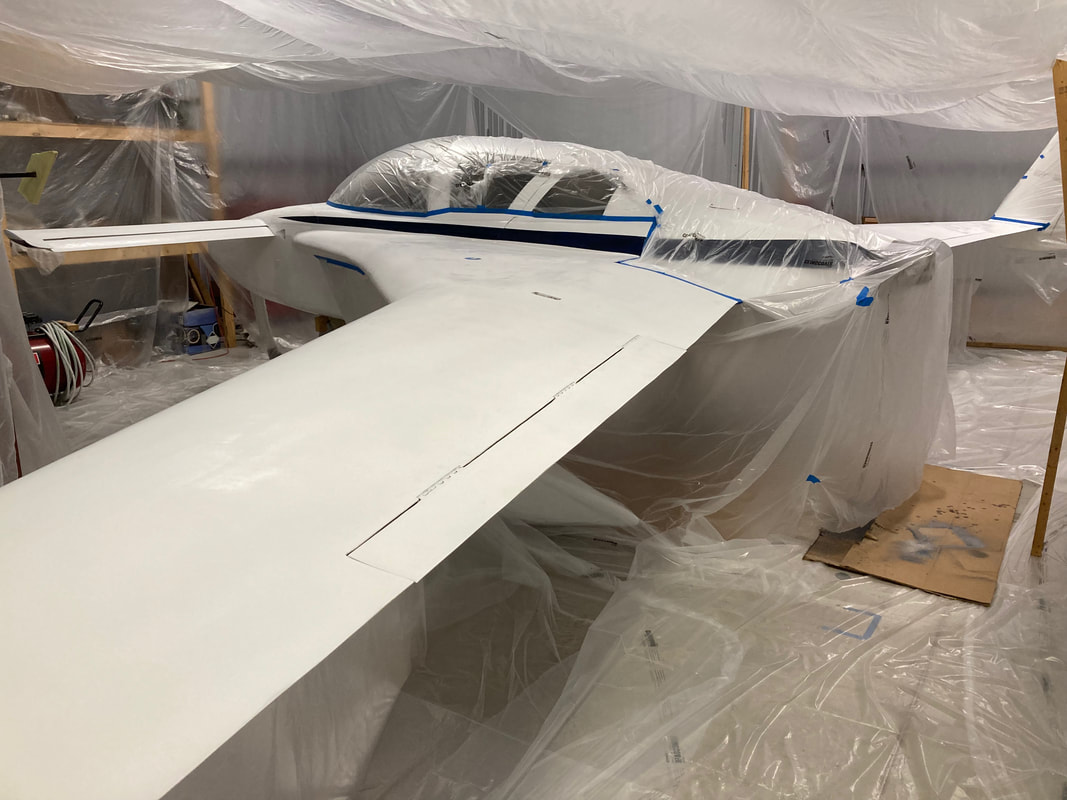
Before spraying: Tent built in the hangar around the plane. I built a spiderweb over the top and draped .7 mil plastic over the web. 2mil plastic on the floor.
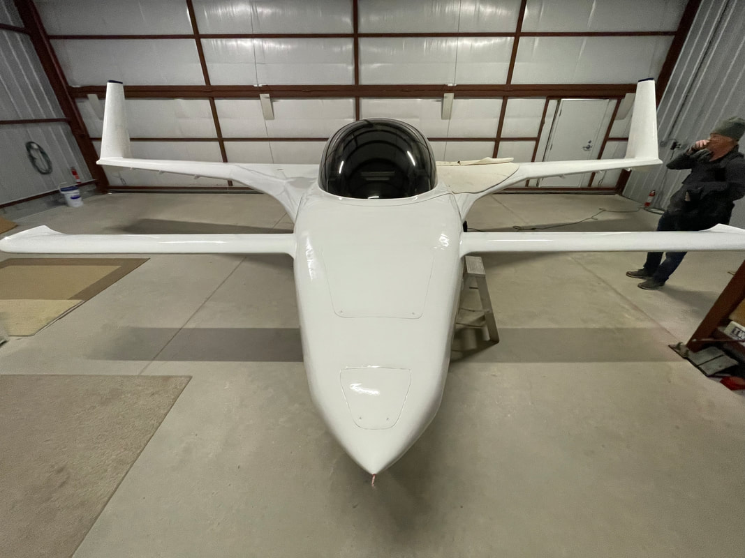
Yes, the 2nd pass gave better results for sure. Not a show plane by any means. Still some drip spots, one orange peal area where I prep sanded but apparently didn't clean well enough after polishing, and a couple of spots I missed re-coating. Still learning. Maybe next summer I'll go back after these spots...
|
|
Checklist Pockets:
The Cozy plans include provision for pockets in the front seat armrests that are really useful for storing stuff. These pockets were designed to carry charts and other somewhat flat gear that one might want access to in flight. Much has changed however in the decades since the Cozy was designed and in N78CZ these armrest pockets primary contents are the battery pack and controller for each noise cancelling headset. It turns out that this battery pack fits perfectly into the bottom of the pocket and is convenient for keeping the headset cable out of the way, given where I have the headset jacks (fwd of the armrests in the instrument panel). What remains that I have typically kept in these pockets are laminated check lists and a couple of barf bags, just in case. These easily fit, but make it a little more difficult to get to the headset battery pack/controllers, so I designed a couple of very think pockets that accommodate JUST the checklists and barf bags so they are easy to access, without using the standard armrest pockets. These are really easy to make. I just pre-formed them with a couple of layers of UNI angled 90 degrees to each other (what I had plenty of) but could also be made with BID. For the larger one on the Co-Pilot side I added a couple more plies of BID on the upper 1.5 inch lip to stiffen just this area where the pocket should not be floppy. The flanges can then easily be flowed to the side of the armrest with my design because the side of my armrests are large flat angled pieces built to the plans structure. The pictures show that I use a small pocket on the pilot side to hold a spiral bound flip checklist set for all phases of preparation and flight, and a larger pocket on the Co-Pilot side for the larger Preflight/Emergency Checklist and the barf bags. |
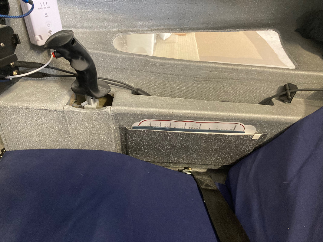
Longer pocket on CoPilot side for barf bags and Preflight/Emergency laminated check list
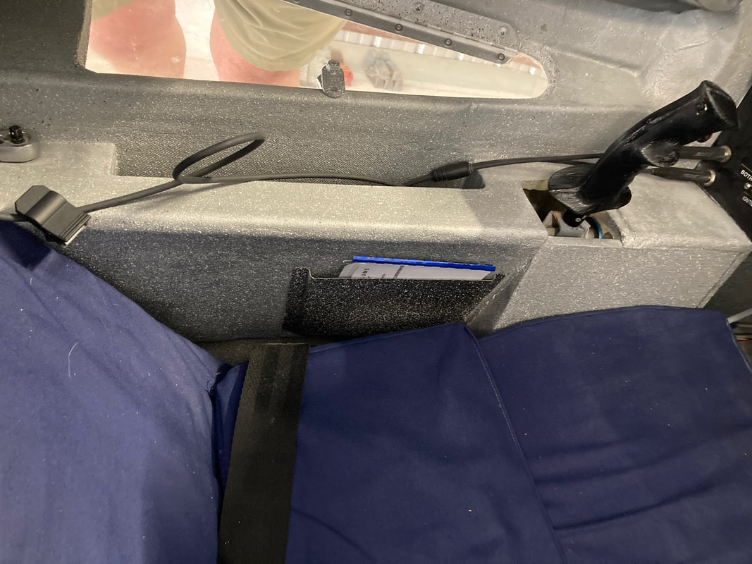
Shorter pocket on Pilot side for spiral bound flip style laminated checklists from engine start to shut-down.
|