Ch 23 Engine / UL520is Initial Integration
How this page is organized:
There are many subsystems and interfaces required to really Integrate the engine. This page deals with all the major elements and notes some of the special things I needed to deal with in implementing the UL engine in the Cozy. Thanks to Nate Mullins, Ryley Karl, Greg Cross and Ray Lawrence who provided input as I dealt with these things. The order of each on this page is not chronological. I dealt with each as I had resources and enough interfaces were available either on the engine, the firewall, or other. Sometimes I had to jump around on these as they matured to insure all the elements worked well together.
There are many subsystems and interfaces required to really Integrate the engine. This page deals with all the major elements and notes some of the special things I needed to deal with in implementing the UL engine in the Cozy. Thanks to Nate Mullins, Ryley Karl, Greg Cross and Ray Lawrence who provided input as I dealt with these things. The order of each on this page is not chronological. I dealt with each as I had resources and enough interfaces were available either on the engine, the firewall, or other. Sometimes I had to jump around on these as they matured to insure all the elements worked well together.
Oil/Air Separator:
UL provides an Oil/Air separator but upon consultation with Nate Mullins, I decided to buy a 3rd party unit from Anti Splat Aero. The name is awesome, and the separator they make is really specific designed to do the job, where as the UL unit is an empty cylinder with some centrifugal input (not likely to be very effective). I mounted it on the firewall near the upper left engine mount interface and pictures of it can be seen elsewhere on this page (it's silver).
UL provides an Oil/Air separator but upon consultation with Nate Mullins, I decided to buy a 3rd party unit from Anti Splat Aero. The name is awesome, and the separator they make is really specific designed to do the job, where as the UL unit is an empty cylinder with some centrifugal input (not likely to be very effective). I mounted it on the firewall near the upper left engine mount interface and pictures of it can be seen elsewhere on this page (it's silver).
|
Fuel System:
Because I'm installing in a canard and the UL fuel install kits are set up for pullers, I needed to custom build all the hoses etc for setting up the fuel system. This turned out to be much more frustrating than it should have been because the installation manual for the engine shows how they connect things with their kit, and I'd missed the place where they indicated the thread specifications on the fuel filter. I struggled a bit with figuring out the right hose fittings to use. Lesson: slow down and take notes as I read. Nate Mullins came to my rescue on a really frustrating day, by helping me decipher what fittings are needed to connect to the fuel filter (different on both ends) and confirmed the 6AN sizing on the output banjo fitting for the fuel pumps. Also note that UL provides 10AN fittings for the oil cooling system and 8AN are sufficient (based on Nate Mullins' experience) and much more common. All the thread sizes are of course metric, so plan for this if in US. On the electrical side, my fuel pumps are powered from a switch on the IP with positions 1-off-2 and a 7 amp circuit breaker. I've also wired a warning light near the switch, that illuminates when both pumps are off, but the master switch is on. Both pumps "off" shuts off fuel at the firewall, even if the engine is running and will be part of safety actions if making an emergency off field landing. |
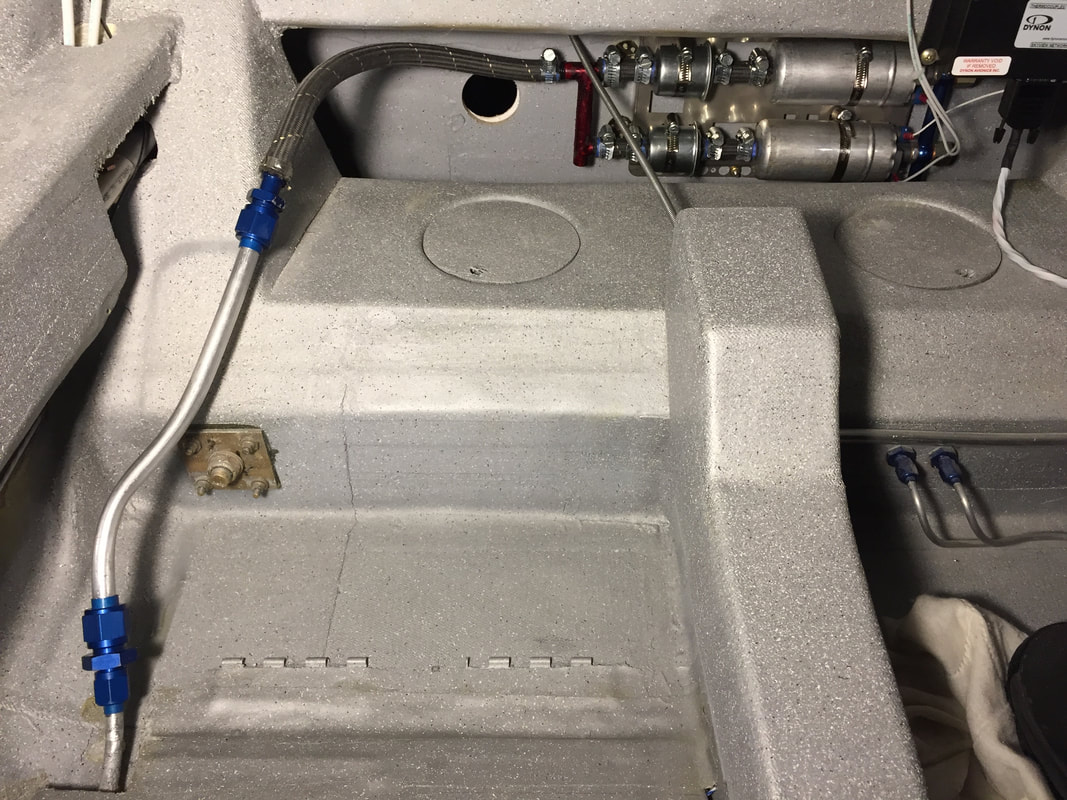
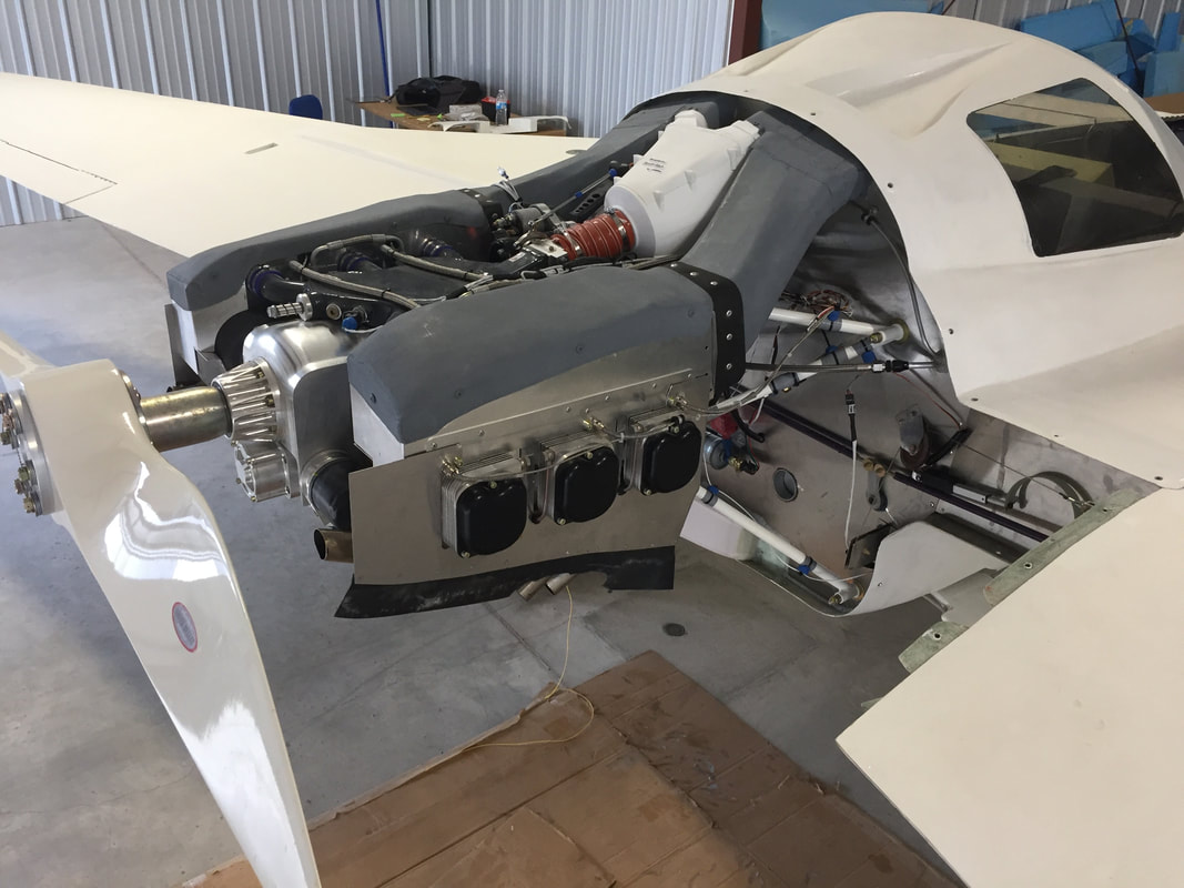
Here's the fuel system starting at the exit pipe from the central sump (dual function as Rt Rear thigh support). 1/2" hard line, to 1/2" teflon lined flex hose, to flow splitter (red) to dual pre-filters to to primary (top and alternate) fuel pumps. From here it's 6AN teflon lined stainless braid hose through the firewall to the main fuel filter/pressure sensor then up to the engine main fuel injection manifold.
The picture is a little confusing, since there's lots of other stuff between the engine and the firewall so I'll just describe the routing here. Excess fuel from the injection system is routed to a pressure regulator then split to return to each side tank. All lines in the engine compartment are teflon lined stainless steel braid.
|
|
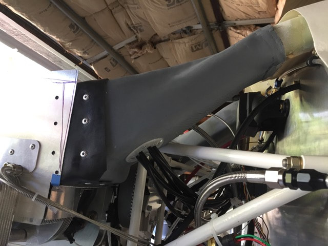
Cylinder Cooling Ducts:
Because this engine's cylinders are downdraft cooled I needed to implement a different cooling method than the standard Cozy (which gets cooling air from the underside of the fuselage). The first step was to return to the Turtleback (TB) and cut the two large NACA scoops in the top, which would feed cooling ducts leading to the plenums over each cylinder bank. Info on the NACA modification can be found at this link. I took some pictures from aft and side and used them (scaled) in CAD to start an approximation of what the duct will look like from the topside NACA scoops to the UL power provided cylinder cooling plenums. The optimal shape is very 3D and I'm also planing to use some of the NACA air to cool the alternator rectifier and provide inlet air to the engine. The resulting design took a number of iterations in CAD and a trial set of ducts fabricated with help from Steve and Steven in the UT Makerstudio using a gigabot 3D printer and PLA filament. Thought this was a slow process, I enjoyed getting much better with Fusion 360 CAD software and learned much that can be helpful with my students. The first prints were used to check for interference and note actual fitting corrections needed for the final parts. A key interference on the left side duct is the oil dipstick, which is positioned for a tractor airplane. I used the 2nd 3D printed prototypes as forms for BID layup of the actual duct pieces, as shown in photo. Then wrapped rubber cowling seal around the aft flange of the duct to make the vibration isolation/seal between the ducts and the plenums (the tops of which are started but not finished in some of the photo's below. 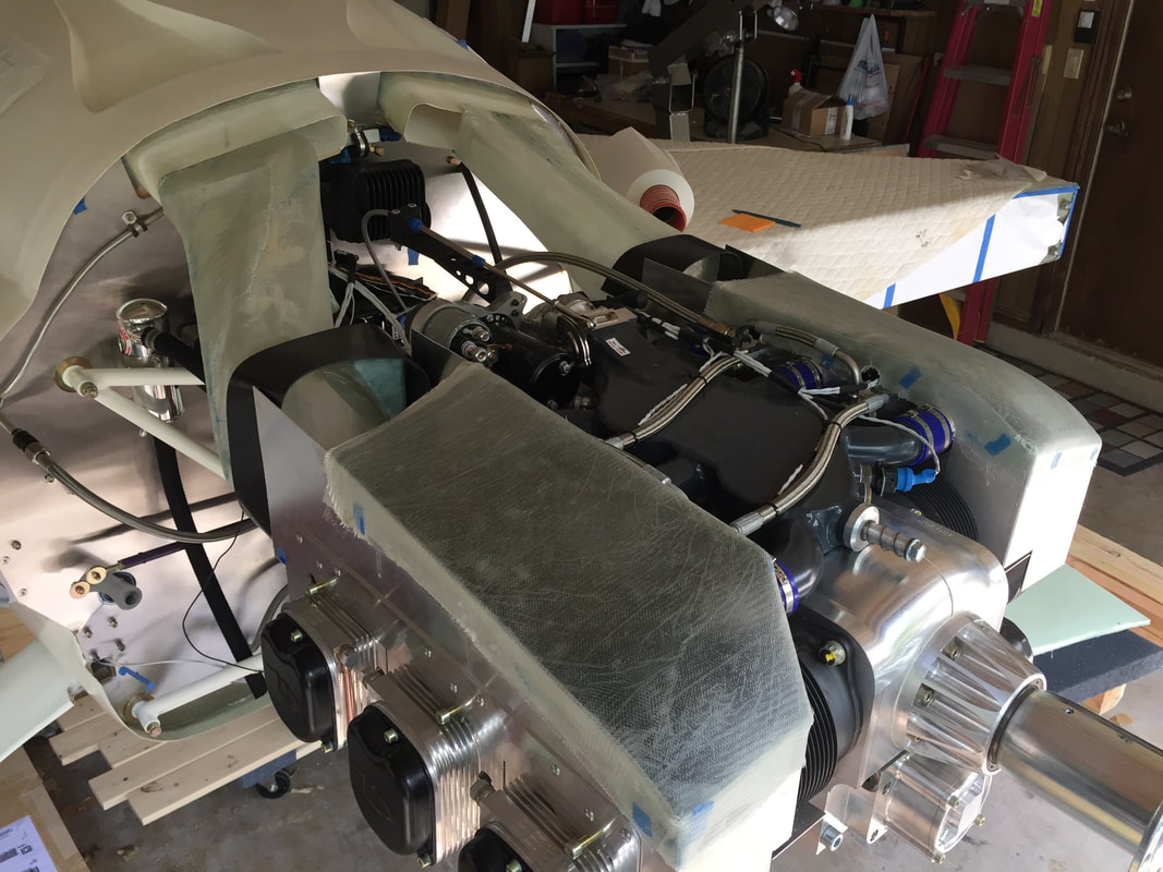
A view of the cylinder cooling ducts in fiberglass form after converting the aft-most profile to a rectangular shape to enable the use of black engine compartment seal as the vibration isolator between the ducts and the plenums. In this picture I've cut the plenum sides down and covered most of the plenum top with 2 BID layers. Some more work to do, so this is just interim progress...
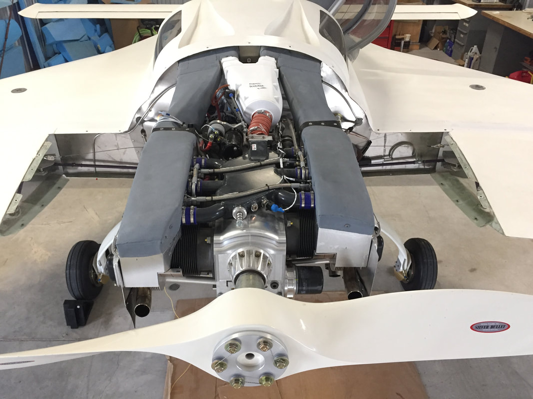
Picture taken much later in the hangar with the plenums and cylinder cooling ducts completed for first flight.
|
Top view of prototype 3D printed ducts, airbox, and rectifier cooler. This was critical step to confirm the CAD was appropriately sized and the shapes didn't interfere with the engine mount while aligning with the cylinder plenum walls on both sides. Clearance around the rectifier is also tight (to force flow across the fins, and this needed a fit check, but worked out well. Actually quite remarkable given the accuracy of measurements I needed to take on the NACA's, engine mount, rectifier, plenum walls, etc. (all of which were referenced to the firewall frame, fuselage centerline, and the lower edge of the rectifier).
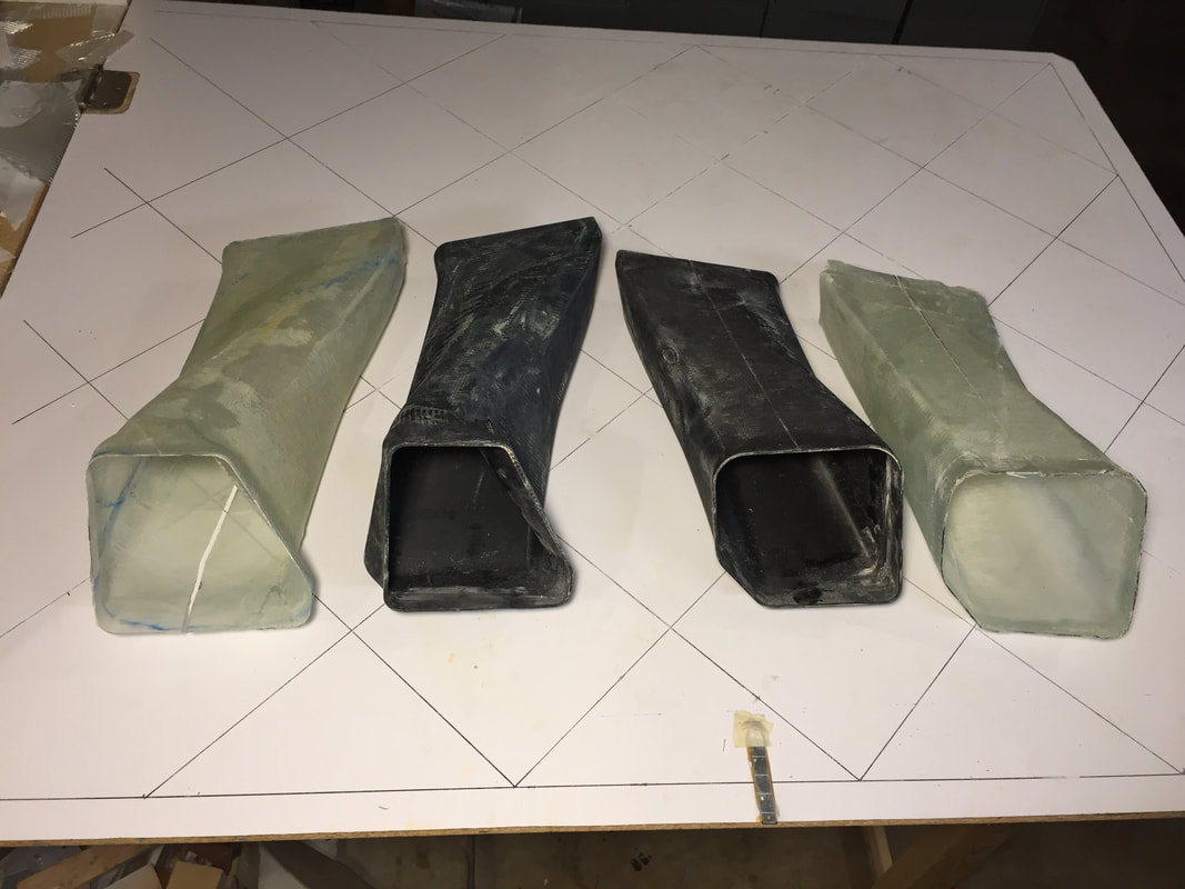
Here's a look at the L and R ducts (green) after peeling them away from the 3D printed forms (black). The geometry is complex, so you can only get them off by cutting the glass (you can see the cut on the bottom of the L duct). This will be glass taped when I reinforce the fwd and aft flanges. I used auto wax as the release agent on the forms.
Another shot of the finished cylinder cooling ducts/plenums...
|
|
Oil Cooling:
I followed the process described by Nate for using a large (I used 17 row Aeroclassics from Aircraft Spruce) oil cooler positioned between the oil sump and the belly NACA scoop. I'll have to build a custom duct from the scoop to this cooler and a diffuser in the lower cowl. I used 8AN hosing with a fire-shields since these are within inches of the exhaust tubes on the lower right side of the engine. To get the oil filter sandwich piece to angle with the tubes exiting down, you have to remove an aluminum tab in the lower part of the engine block. The cooling flow for this heat exchanger will come from the belly NACA, since I'm providing cylinder cooling from the top for the UL engine. I'm not using all of the NACA area, and will decide later what to use the extra for, or just fill in part of the belly NACA that I'm not using. I'd like to use this part as a direct 3D print, since it's not close to exhaust and is just carrying ambient air. I'll decide after I have the prototype fitted, whether to make a separate glass duct using this shape as the form/plug. After fitting the original design I modified the design to make the inlet area more closely match the presented area of the cooler (the original design was 30% oversized, and I don't need this in the high pressure belly area. I also increased the internal strength of the design by including 3 deep internal vanes (only one shallow one in original) that connect the upper and lower duct walls. This newer design looks really good. As I started to work on the diffuser for the flow aft of the cooler, I really started to think more about the profile of the cowling in this bottom area, and I think I'll have a much better cooling system by lowering the cooler slightly and facing it more fore/aft, while keeping it inside the cowling line. This means a re-design again on the duct and the mounting bracket for the cooler and I'm going to postpone this until I have the engine running, since it's not required for static testing and finding ALL the things that need to be addressed further for mobile/ground testing. There's more pictures and description of this in the cowling page where I was working on the interface and finalizing the exhaust duct... |
This is the FIRST location I mounted the Oil cooler: attached to engine mount (silver hoses not connected yet). It's bolted to an aluminum frame that's attached to the lower cross tube of the mount at the engine, and you can see an angle brace connected via Adel clamp to the far side support tube. This set the stage for lots of measurements to design the cooling duct from the belly NACA to the cooler (see CAD below).
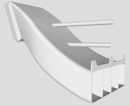
This is stl image of the cooling duct design. When I moved the cooler down and tilted it forward, I still used this design, and just adjusted the flange location/orientation. The 2 cylinders sticking out of it are "supports" needed when the prototype is 3D printed and are removed before fitting.
Close-up of the oil cooler inlet duct prototype (left side bolted to front face of oil cooler, right side aimed down the middle of the belly NACA duct).
|
|
Exhaust System:
I modeled my exhaust from the approach Nate took in his LEZ, with 4 forward cylinder exhaust tubes exiting the bottom of the cowling and the #1&2 exhaust tubes exiting aft just inside the cowling. This required matching each tube to it's exit location in the cowling, which was a multi-step process, as the cowling shape was being developed simultaneously. Some degree of freedom in rotation of the tube within its flange before tightening was helpful here. By trial and error and good luck with eyeball, I switched the tubes around and tried different flange rotation angles and found combinations that worked. All of the original UL down tubes had to be trimmed to an appropriate length, and 3 of them required cutting and re-welding to get the curves I wanted at the places I wanted. I used trimmed pieces for this and Janelle Engle at UTexas was the artisan who performed all the welding. Thanks much Janelle! I'll get a picture of the final configuration soon, but below are a quick couple of pictures I took after a couple of iterations of the initial fitting/trimming process.
|
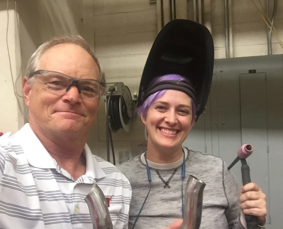
Janelle's excellent welding work on the short pipes (in foreground)
|
|
Throttle:
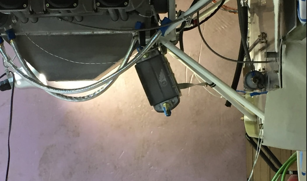
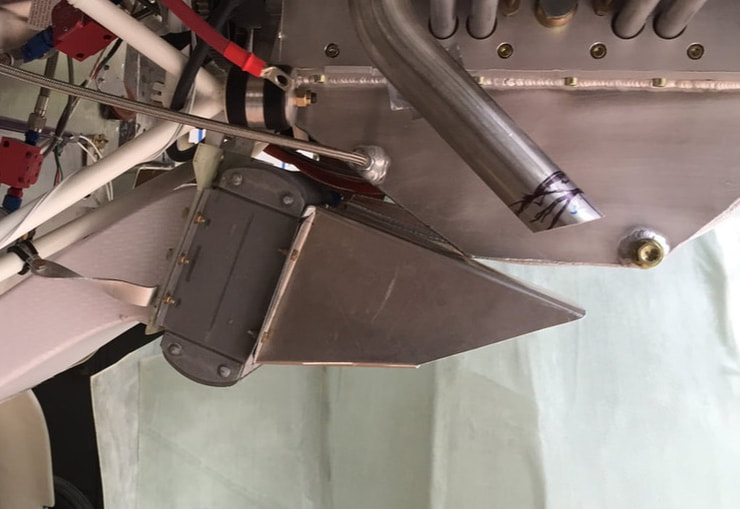
Ordered a 9 ft push/pull control cable and end fittings. The length appears to be great in quick fit check. Detailed brackets for both ends are needed, but I'm not going to get into this until I make further progress on the Air Ducts and plenum described above. I have allowed for some clearance between the engine intake airbox and the cable, but it's going to be tight in this area. I did a quick installation of the throttle cable when it arrived to make sure that it was appropriate length and that I could build brackets both on the engine end and the quadrant end to hold the casing for the push/pull actuation. I then pulled the ACS purchased quadrant (see way back in Ch ?? when I built the custom mount for the quadrant to fit in my center console) and had to re-design how it pivots (pivot from the bottom of the lever) to match the direction of throttle movement of the UL engine in pusher configuration. I custom designed a block/clamp that bolts inside the center console to hold the forward end of the push-pull, and the more complicated bracket/clamp (see picture) that mounts to the engine near the starter, and holds the aft portion of the push-pull and aligns with the spring loaded throttle on the UL engine. |
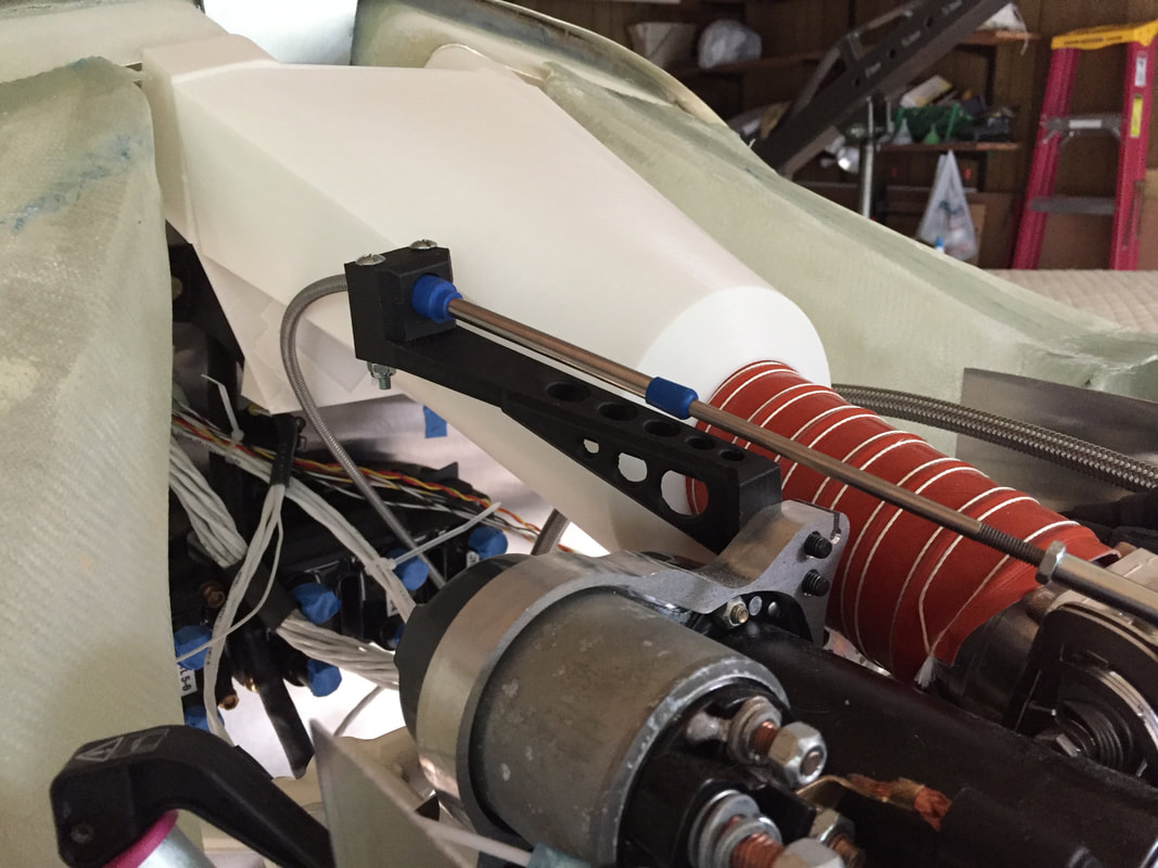
Throttle cable clamp/bracket mounted and holding the push-pull cable running from center console. I custom designed this bracket and 3D Printed it in Carbon Fiber reinforced Onyx material on a Mark Forge machine. I will likely make a replacement bracket (using what I learned form this design) out of Aluminum (for heat resistance)
|
|
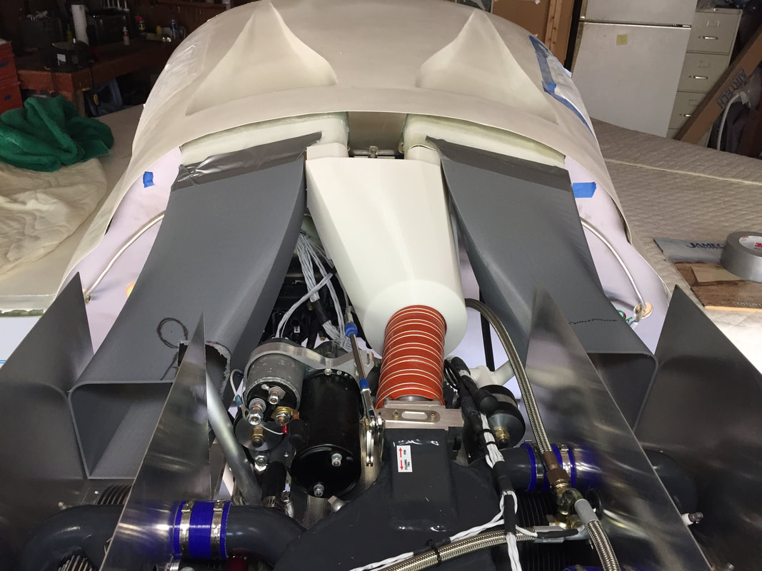
Air Intake and Rectifier cooling:
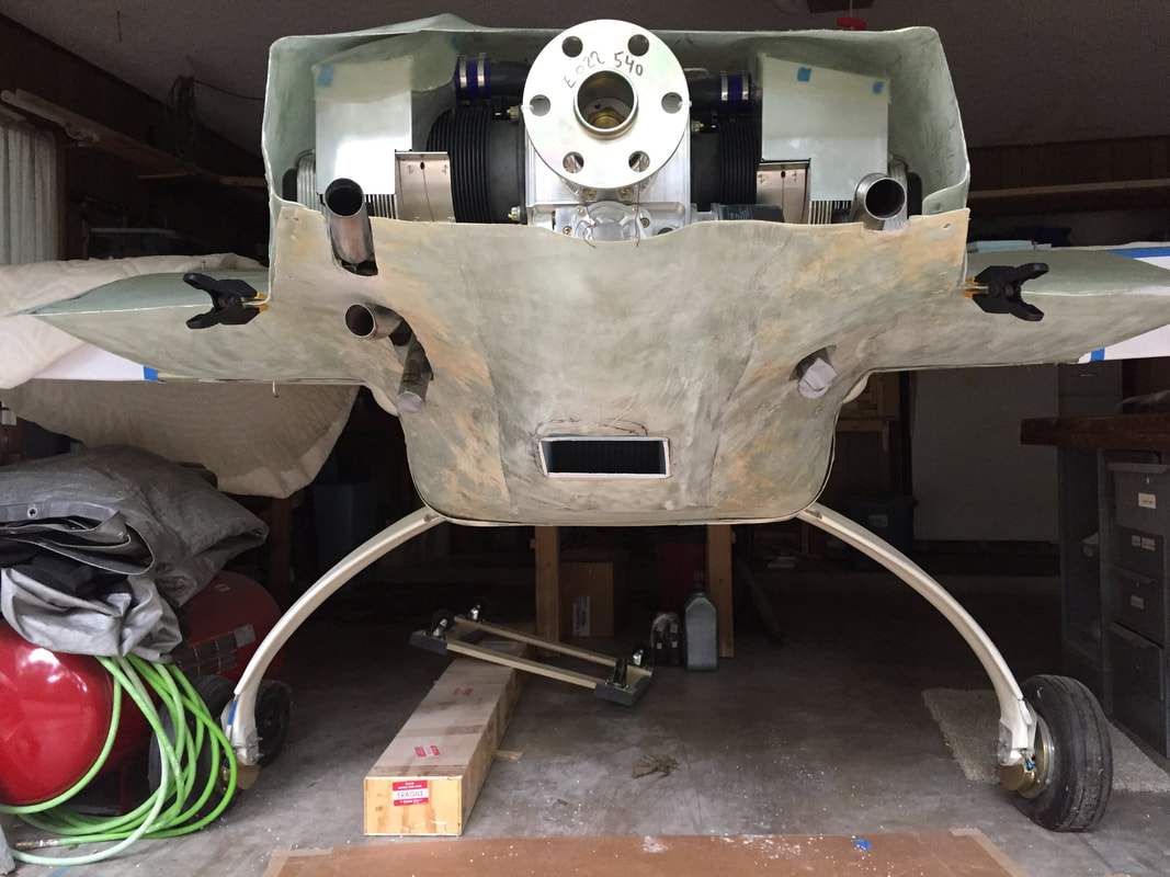
I noted above how my implementation used the engine cooling method (NACA scoops on the roof), and one can see in the pictures that I did not use all of the scoop area for cylinder cooling. This was because I planned early on to use this cool air for multiple purposes. The rectifier was mounted close to these ducts as shown back in the firewall preparation page, and the engine itself needs a significant supply of air to breath and make power. I designed and developed a custom airbox to tap the inboard unused area of the roof NACA's and also divert a small amount of air to the cooling fins on the rectifier. A look at the integrated design (in CAD) of the airbox and the cylinder cooling ducts is shown to the right. |
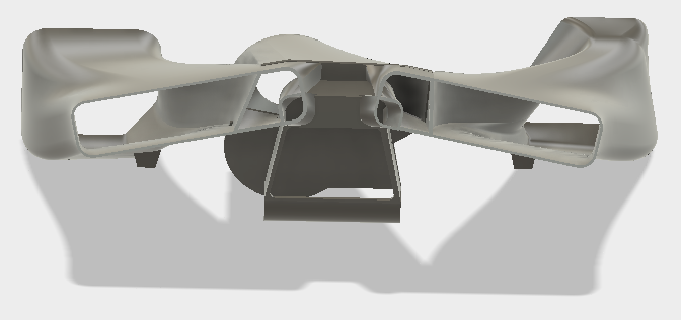
CAD view from front (firewall side) and a little above showing the flow path from NACA trailing edges to the cylinder plenums on each side. The inboard portions of each duct are partitioned to feed the airbox/air filter, and a small diversion of air to the rectifier (small almost circular openings on the lower/inboard corners).
|
|
Electrical: Starter/Alternator/ECU/Ignition/Sensors and Integration with EFIS
Starter: nothing fancy here. The starter is wired per UL directions, and since the starter solenoid is right next to the starter, I routed a (2 awg) cable from the master switch to the solenoid. There's a separate signal wire to the Dynon HDX that convey's when the starter is actually operating (presumably for display). The stater is grounded to the engine, which is hard grounded (2 awg) from near the starter via cable to the battery ground terminal. Alternator: The alternator is also pretty straight forward since UL provides an integrated permanent magnet generator and rectifier. The cable from generator to rectifier is provided and the connector pre-wired with 10awg. Rectifier DC output cables are also provided, so all needed is clip cables to length and crimp on ring terminals to interface with the main power bus/battery ground respectively. IMPORTANT: the rectifier has cooling fins and the installation instructions require these fins be exposed to air flow (though OK to mount in the engine compartment). Nate Mullins told me he had a rectifier fail because it didn't have adequate cooling so I'm planning to use a little air from the cylinder cooling ducts to cool the rectifier. See the cylinder cooling Ducts section above for how I did this. Ignition: All ignition wires were routed from the coils to the plugs through the bottom of my cylinder cooling ducts. UL provides a nylon disk for sealing the opening in the aluminum plenums and I just used these riveted into the bottom of the cooling ducts (see picture to right). Note that a couple of the connectors that mate with the ignition coil blocks didn't seat all the way, and UL sent me replacements that worked fine. Sensors: The sensors I have installed are: fuel pressure, oil pressure, oil temperature, CHT's (6) and the standard voltage and current sensors. I just followed the UL ECU and Dynon EMS installation instructions. - Note that there is some interference between the oil system thermostat (in the oil filter mount that has flow diversion to oil cooler) and the oil temperature sensor, when the cooling lines are run low and forward to the cooler in a pusher configuration. Nate used an oil diverter that doesn't have a thermostat so his interference was much less, AND he is running a Garmin compatible oil temp sensor, which is smaller than the Dynon sensor I have. I resolved this by allowing my diverter to face more downward, so the two don't touch, and I think it will be adequate (but requires a little more cowling bulge here). |
Ignition wires entering the right side cylinder cooling duct from below through the white nylon disc supplied by UL Power. The disc was pop riveted in place.
|
|
Propeller:
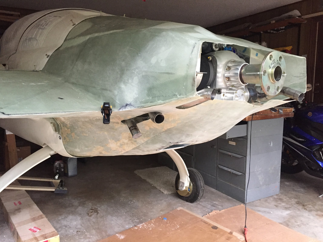
I have a loaner prop (68Dx75P) from Gary Hertzer for ground testing and data collection. This prop is likely too big for the 520is, based on the experience of Nate Mullins, so it may be replaced with something more along the lines of a 65x76, which Nate has had very good performance experience with on his Long EZ. I have the 110 mm prop shaft from UL and am not running an extension as my prop is at the plans distance from the firewall. I finally tested this prop to full power much later when I had the airplane fully assembled and ready for flight at the hangar. The result was only being able to get 2300 rpm static at full power. I got in touch with Gary and we'll have a 65x76 made for flight use. More on this will be posted in Ch26: Hangar/More Punchlist Stuff page, when I have it. |
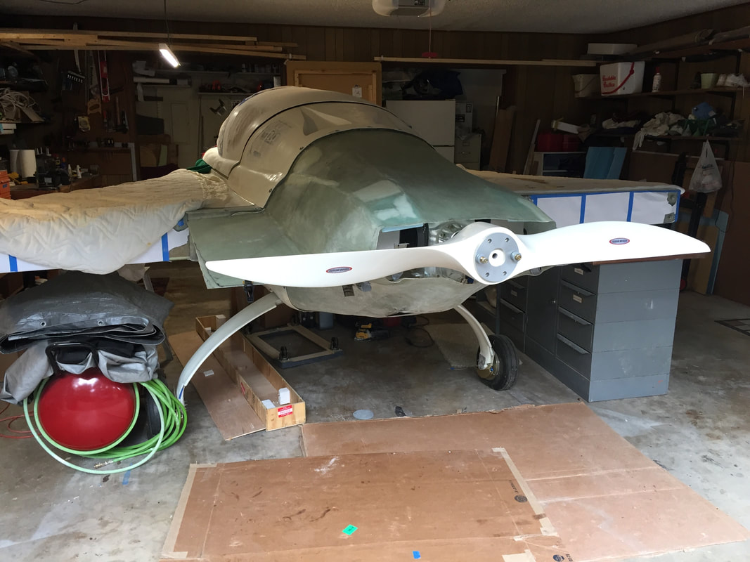
Even though this is only a loaner and a little large in diameter, it will work for early engine checkout. It's not fully bolted on here, but it's nice for giving me motivation to get the engine running and move to the hangar.
|
Once I had Installation complete enough to get the engine running and incorporate the final exhaust system, oil cooling system and cylinder ductwork, I started on the custom cowling.