Ch 23 Engine/Firewall and Mount
Fuel Supply from Sump through Firewall:
This subsection covers installation work for the fuel system components between the center sump and the firewall. When I changed plans from using the Lycoming to using the UL engine, I no longer need the airflow performance pump and sold it to Andrew Anunson who's already fitting out his Lycoming but had not yet purchased the fuel pump. I kept my airflow performance serviceable fuel filter (40 micro) as I'll use it with the dual UL electrical pumps that come with the engine. I arranged with UL to have some of these auxiliaries shipped to me early so I could work on positioning them on the firewall before the actual engine arrived. Ray Lawrence of UL was super helpful and sent the fuel pump bracket and pumps, pre-filters, the post pump fuel filter, the alternator power electronics module that mounts on firewall, a mockup of the ECU, and misc other things. What I don't need, or gets duplicated in the engine shipment, I'll return to Ray. I've mounted the firewall studs (Rotaloc brand ordered from McMasterCarr) but just haven't gotten back to actually getting everything mounted. I'm trying to figure out how much stuff I want to get mounted on the firewall, just to remove it all when I have to get the fiberfrax and SS sheet fitted. See below on Fiberfrax/SS fire shield section where I talk about my approach to minimizing engine mount/dismount/mount. More on this is covered in the Engine Installation page.
This subsection covers installation work for the fuel system components between the center sump and the firewall. When I changed plans from using the Lycoming to using the UL engine, I no longer need the airflow performance pump and sold it to Andrew Anunson who's already fitting out his Lycoming but had not yet purchased the fuel pump. I kept my airflow performance serviceable fuel filter (40 micro) as I'll use it with the dual UL electrical pumps that come with the engine. I arranged with UL to have some of these auxiliaries shipped to me early so I could work on positioning them on the firewall before the actual engine arrived. Ray Lawrence of UL was super helpful and sent the fuel pump bracket and pumps, pre-filters, the post pump fuel filter, the alternator power electronics module that mounts on firewall, a mockup of the ECU, and misc other things. What I don't need, or gets duplicated in the engine shipment, I'll return to Ray. I've mounted the firewall studs (Rotaloc brand ordered from McMasterCarr) but just haven't gotten back to actually getting everything mounted. I'm trying to figure out how much stuff I want to get mounted on the firewall, just to remove it all when I have to get the fiberfrax and SS sheet fitted. See below on Fiberfrax/SS fire shield section where I talk about my approach to minimizing engine mount/dismount/mount. More on this is covered in the Engine Installation page.
Engine Mount
|
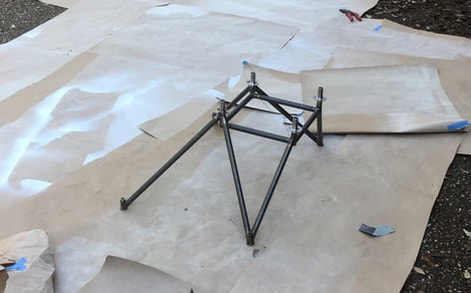
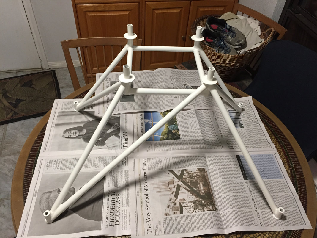
I was really fortunate that Ryley Karl had already been through the design process for integrating a UL520is on the Cozy MKIV. He graciously shared his design with me and I kept his dimensions exactly as I'm planing a similar engine placement and prop extension (more on that when I get to the prop). I'd been working with Ray Lawrence of UL Power in Georgia on the engine setup and he arranged the fabrication of the mount with M&W Machine and Welding in North Lewisburg, OH. They had done several other UL engine mounts which share very similar geometry and connection pins on the engine side with the 520is. They did a wonderful job on the mount and I had it in 4 weeks. I painted it with the same white epoxy primer I used on the rest of the plane. The mount weighs 7.8 lbs painted. Here's a before and after shot for the paint, until I get something more interesting to show...
|
|
Fiberfrax and Stainless Steel Fire Shield
|
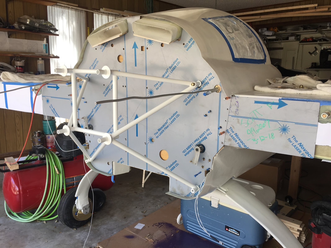
The plans call for fiberfrax and Al flame shield to be installed on the engine side of the firewall, but most builders now use a stainless steel substitute for the Al element due to the higher melt temperature of SS. I'm following this SS path. I'd like to avoid mounting the engine, then getting everything integrated with/through the firewall, and then dismounting it and the mount from the firewall so I can apply the fiberfrax and 304 SS shield. The hazard with this strategy, is that if you don't think of everything you need to mount on the firewall beforehand, you may not have all the holes in the SS or have them in the right locations later. Also, getting at the firewall with the engine/mount in place is harder later for making any holes you forgot. So I'll document what I did here to minimize my risk here. As the build progresses, I'll also document any mistakes made or post mounting modifications I had to do.
The first step for me was to get everything I've already done on the firewall documented digitally in CAD. I'm going to water jet cut my SS panel so accuracy is important for every single hole as well as the peripheral contour. I'd used a similar procedure to make my vinyl IP cover with all the labeling so I knew this was an important step. This time I used a 35mm SLR with a zoom lens and took the picture of my firewall from about 50 ft away, to minimize optical distortion (I got some of this using my phone camera to take pictures of the IP...). This image was brought in to Fusion 360 (Autocad) and used as a template to sketch the peripheral curves with splines and insert holes for the following: - existing studs for rudder cable turning blocks - engine mount bolts - engine wiring harness - starter cable, ground cable, and alternator charging cable - throttle cable - bolt holes for the alternator rectifier, and ignition coil blocks - fuel line - hole for heater muff tube - small holes for fuel vent tube Adel clamps - holes to slip over fuel vent tubes and fuel return tubes on each side I still have the access tunnels on either side below the rudder cable exit. I then printed the sketch pattern with all the holes at full scale in paper and applied it as a template onto the firewall to see how well the CAD data matches the actual hole/stud positions and periphery geometry that exists at this point. Some minor corrections were noted on the paper with a red Sharpie pen and adjusted the CAD. I got a 3ft x 4ft sheet of 304 Stainless Steel 24 gage locally and had it waterjet cut from the updated CAD (including holes for riveting the side wings). Note that Marc Z has suggested that 26 gage is sufficient, but I couldn't get it easily that thin. the weight penalty of using the slightly thicker sheet is probably at most 2 lbs. The resulting shield is shown in figure to the right with the engine mount also held in place with un-tightened bolts. Then I made all the holes through the firewall using the SS as template (accept the bolt holes for the ignition coils - which I'll do when the coils arrive with the engine). Also note that I needed to cut a slit in the SS from the closest edge to each of the aileron torque tube bearing holes to allow slipping it over the crank arms without removing the crank arms, which fit pretty tight in the bearings. Next I used the SS panels as a template to mark and cut the fiberfrax (easily cut with scissors or a razer blade). I riveted the wing panels onto the main panel, and then applied the fiberfrax to the "front" of the SS shield and then re- installed it on the firewall. At this point, I waited for the engine and firewall components to continue in this area. See UL520is Installation. |
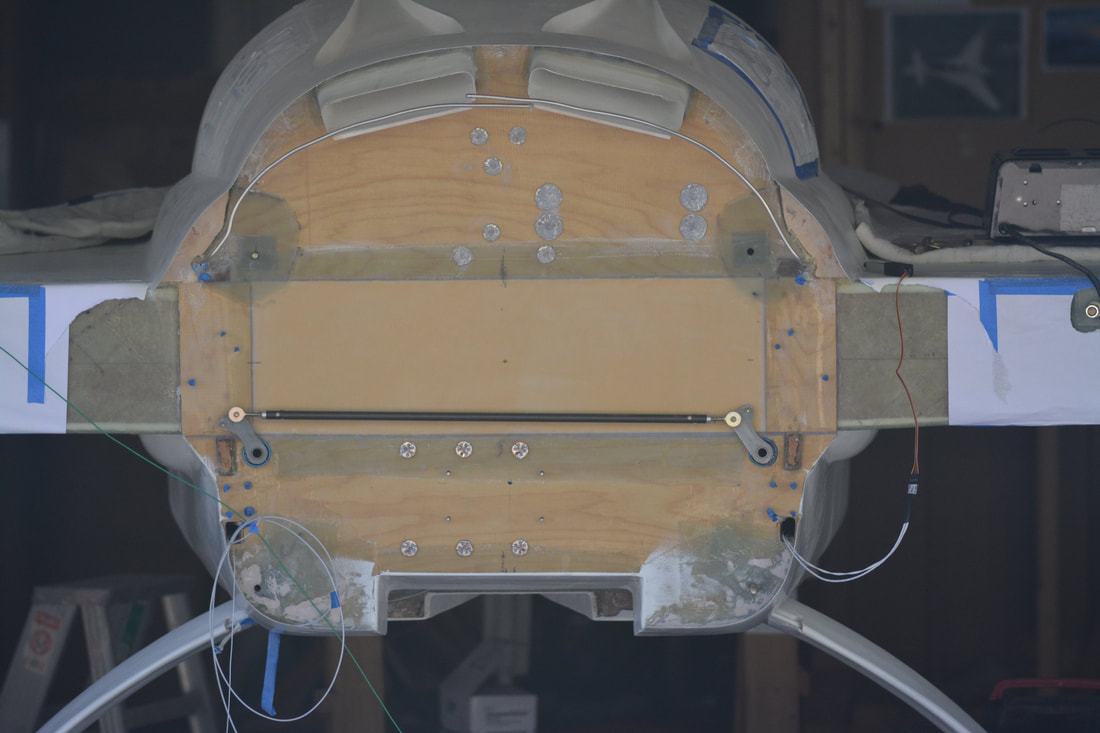
Photo of firewall used to locate the engine mount holes, and all the studs already emplaced for the fuel filter mount and the rudder cable turning block brackets, and aileron bearings, and fuel vent/fuel return lines, and peripheral shape
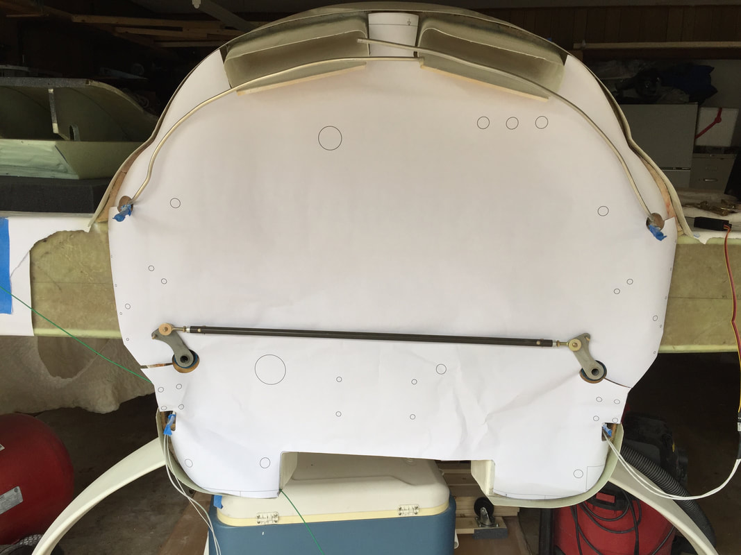
1st draft paper template derived from the CAD with initial ideas for additional holes (2 AWG cable holes, engine harness access hole, fuel line hole, and heater air hole. More will be added and adjusted now...
SS firewall shield trial fit along with engine mount (fuel vent tubes straightened to slip the shield over). SS still has protective plastic covering on it...
|
|
Receiving Engine:
The engine will arrive at my house so I can do as much as possible with it's integration before moving the fuselage to the airport. It arrives by ground freight from MO where UL North America has it first imported from Belgium. It arrived 4/5/18! Yea. Finally. Great crating and no apparent damage. Remove top and sides of crate and easy to roll around the garage on a simple moving dolly. Installation of Ignition Coils and Rectifier: Before mounting the engine on firewall, I mounted the ignition coils and the alternator rectifier on the firewall. The holes for the ignition coils had been designed into the SS shield but not drilled through the plywood portion of the firewall. Everything fit well. The coils are mounted just above the spar, biased to the left side to avoid interference of bolts with the battery on the other side of the firewall. The rectifier was mounted high on the centerline with just enough room to run the fuel tank vent tubes between it and the cylinder air cooling ducts. |
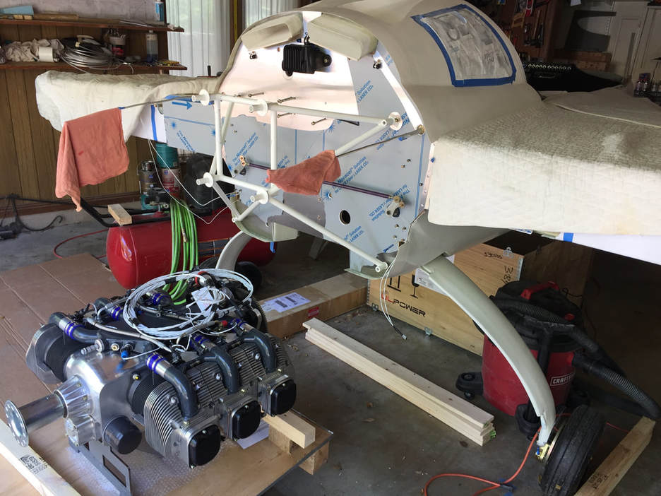
A view of the mount on the firewall: The rectifier (black box) can be seen mounted between and below the upper NACA scoops, and the bolts for mounting the ignition coils can be seen sticking out of the firewall near the level of the upper portion of the engine mount. The red rags are to prevent me bumping and bending the fuel tank vent tubing, which is straight so I can slide the stainless steel sheet onto the firewall.
|
|
Mounting the Engine:
John Nodler (who helped me move the wings to the hangar) loaned me his engine lift shortly after the engine arrived. More on this when I actually use it... When I trial fitted my engine mount to the engine (with the rubber isolators installed) I found a little interference between the top and side cross tubes and the starter/ring gear. I had a suspicion I would have this problem when I received the mount, as these tubes were not welded where Ryley Karl had shown them on the drawings. The cross tubes were all welded at the forward end of the UL engine mount tubes which I presume were procured from Wicks. I think the length of the pins in my mount must be shorter than those used by Ryley, because his top tube is welded in a similar position at the forward edge of the top pins and he clears the starter and ring gear (just barely). At any rate, the interference is small and these cross tubes are primarily to hold the pins in position relative to each other, and don't carry the major engine thrust/torque loads to the firewall. My solution is to remove the material in these cross tubes where the interference occurs and seal them up and that's it. The tubes are still quite strong in tension and and with the exception of the top tube, quite rigid in bending as well for their relatively light loading once connected to the engine mount plate. The picture to the right shows my mount with the material removed and the tubes sealed and primed again. I also chose, at recommendation of Ray Lawrence/UL Power to use 3/8" bolts on the engine side of the mount rather than the UL standard 5/16" bolts. They are a little tight inside the tubes after reaming the interior flange but still fit. In hindsight, I think the 5/16" bolts are fine given that they are working with a rubber mount, but these bigger ones will not cause any concern. |
A look at my engine mount from the engine side prior to primer application but after material removal and micro fill/seal to prevent rust. This material was removed form the cross tubes between the engine mount tubes to provide clearance for the starter ring gear and pinion (top left). These tubes don't take the main engine loads and are still very stiff/strong with this material removed.
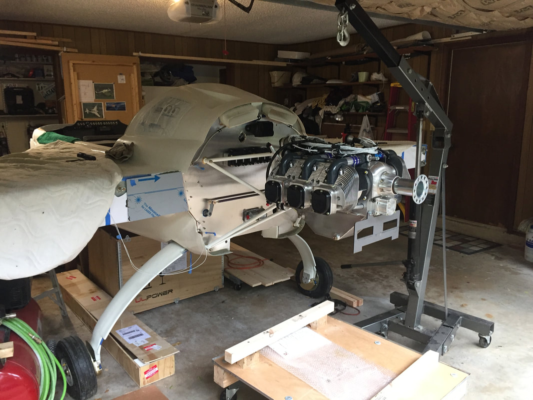
Woo Hoo! It's mounted. Alignment looks great and I had to ballast the nose with a couple of 20 lb wts just fwd of F22 to keep it safe from tipping back. I'm keeping the lift tied loose for safety after taking this picture...
|
Engine Integration Page next...