Ch 18.3 Latch, IP Cover and Misc
|
|
|
Step 17 Canopy Lip and Instrument Cover
I followed the same process as Bernie Siu on the instrument cover by merging it with the canopy lip. The reasoning here is that the FT is relatively easy to remove with the hinge pins on either side, and this eliminates a path for water to get behind the IP. It's a slight deviation from the plans, but I think it takes less effort as there's no interface to build between them and these are not structural parts. I did have a problem even though I laid up the lip with the 1/8" gap per plans, with having the canopy touching the FT lip/IP cover at their intersection when all completed. I've included a picture of how I did this gap during the layup with hand worked cardboard coated with packing tape to enable release. If you are interested in using a similar technique (it worked well, I just should have left the gap at 3/16" rather than 1/8" since a little space here doesn't hurt anything and just makes fit easier later) contact me for more information/pictures. I'm planing to use glass cockpit so good shade on the instrument panel is a priority. I extended the plans IP shade from 1" to 4.5" over the center switch section and 3.5" over the sides. I angled the shade sections such that they would roughly align with my view perspective sitting in the pilot seat (assuming some padding. This is not a simple layup shape. Play around with it in foam first (I used left over thin blue wing foam from the Eureka packing left over from winglets since(I had skipped forward to Ch 20 before returning to canopy section of Ch 18. Once I had the shape I wanted in foam, I built an pattern on paper (bending it around the curves) to help me cut appropriate shapes in BID. Remember that the foam is all throw away when you are done. I used packing tape over the IP joint and any joints between foam, and then laid pallet wrap over the foam area before doing laying pre-wetted 2 BID (with 3 BID from shade portion to 2" forward of the IP line). Because I wanted to bond to the canopy lip, once I had the glass laying right, I went in and carefully trimmed back the pallet wrap to right close to the foam line so that I'd have a bond to the lip portion. 'Careful hand work here to keep from messing up the glass. then cure. I didn't force the glass/pallet wrap down too hard into the corner of the behind panel bump and I think it looks better with no loss of function. Here's what my foam and finished IP cover looks like. I also used Bernie Siu's tip for using push pins to hold the glass temporarily against the under side of the foam to form the rounded edge towards the crew (I used about 18 pins for this shape). 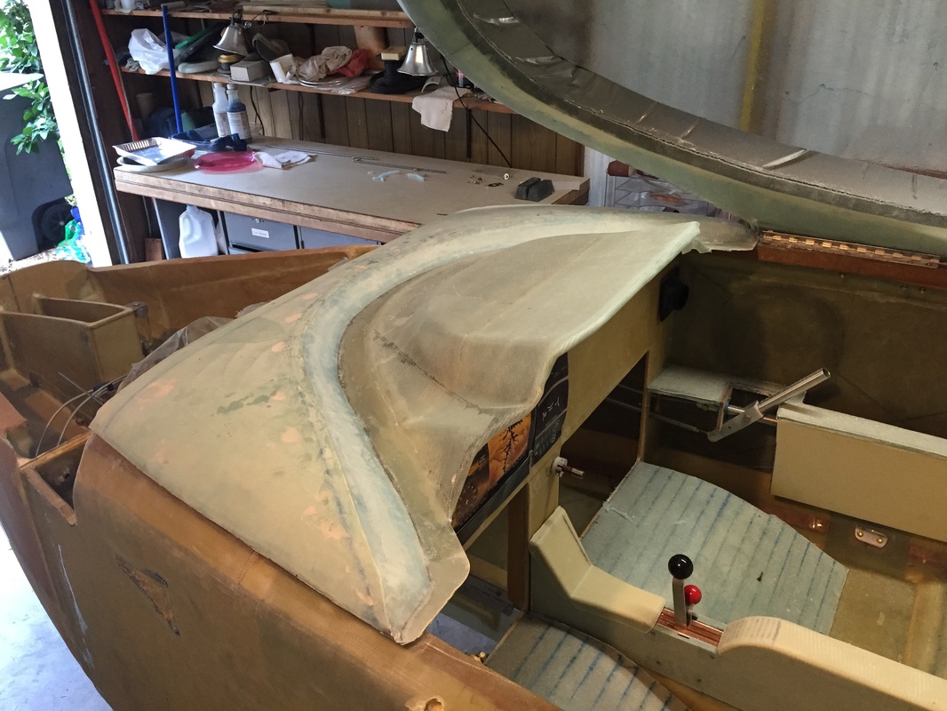
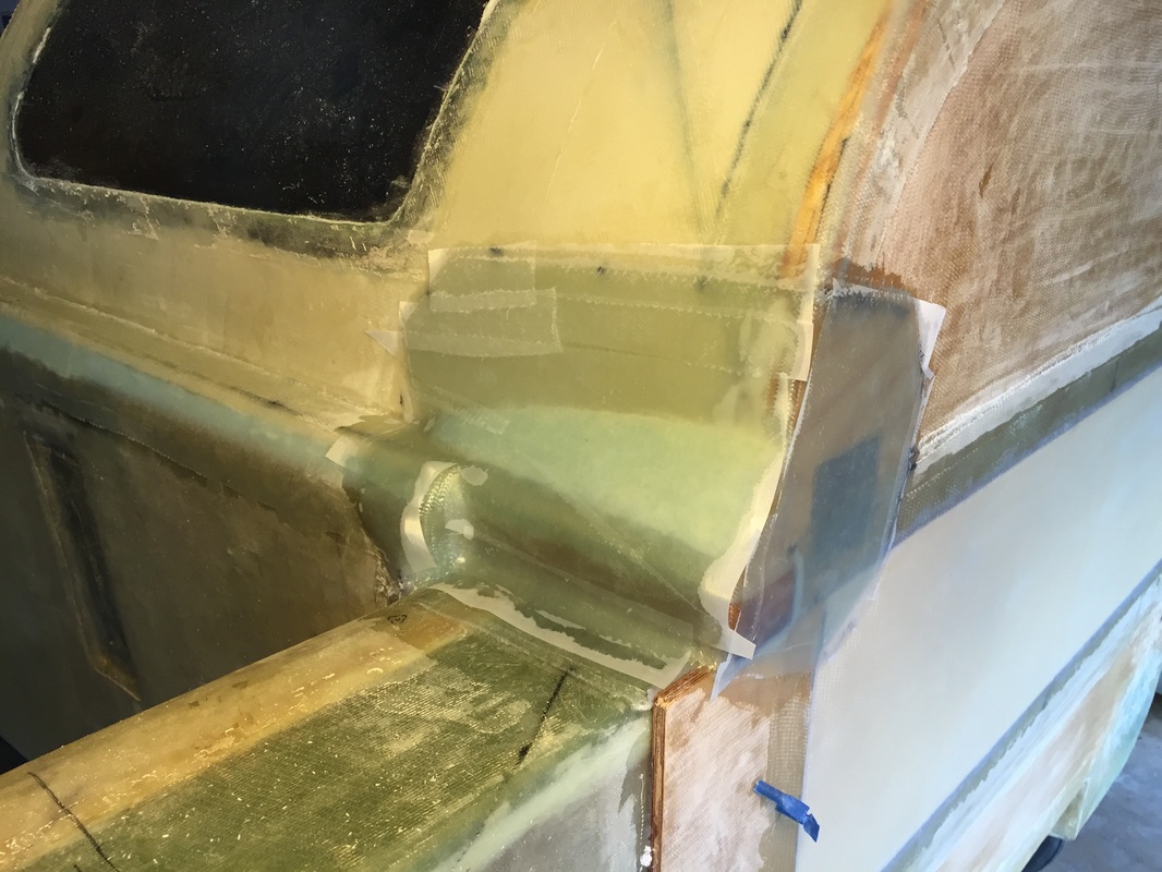
Post layup and peel ply removal for one-piece FT-IP Cover
I later made a couple of small gap filling foam pieces to match the final profile of the IP cover (near sides of elevated switch panel section), and had to cut in along the drip rail to get the canopy to come all the way down to the IP. This was not a flaw in the single piece FT/IP cover, but poor management of the standoff of the drip rail when it was laid up, and having the foam of the canopy frame being a little thicker than desired. See later picture to the right
|
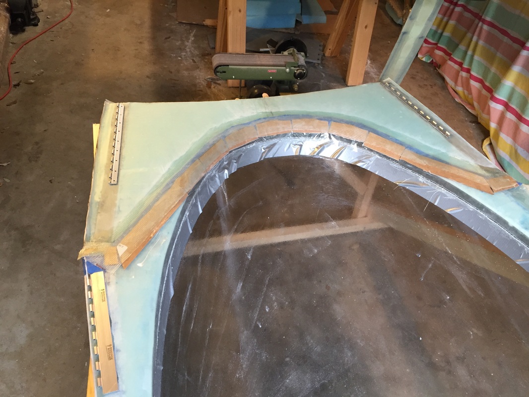
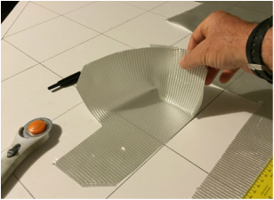
pre-layup view of 1/8" gap and release preparation for the canopy lip. Brown is hand softened cardboard covered in packing tape for release.
Finished canopy lip
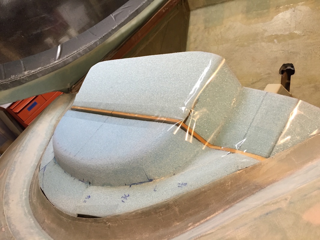
Foam and tape configuration for IP cover layup
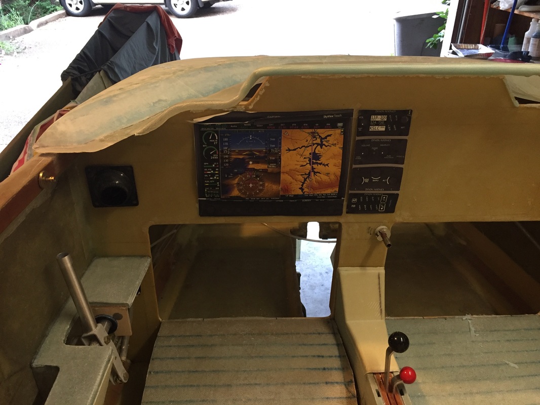
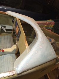
IP Cover viewed from about where Pilot's eyes will be: can see all of instrument panel, but well shaded from sun
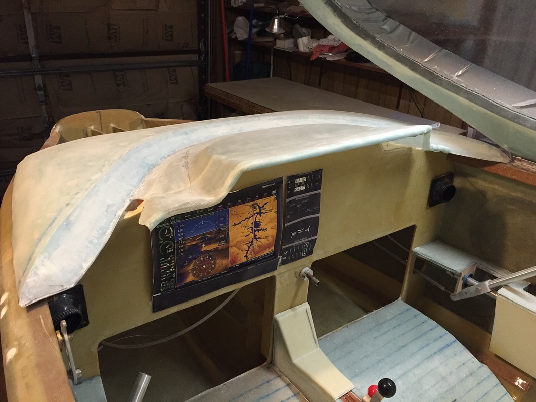
I'll come back later and fill in with a single BID layer the cut-out on left and right of the drip rail in the IP cover. These had to be made along with shaving the top of the IP at these locations, to get the canopy to close without interference.
|
Step 18: Access Door
I'm trying to avoid cutting an access door. I'm considering Cozy Girl Strakes which would come up into the access door space anyway, but even if I wasn't doing that, I'd probably want to use the access door area for a window. If I later build an access door or come up with a way to do the unlatching of the latch mechanism I'll either document it here, or in the latch mechanism section further below.
I'm trying to avoid cutting an access door. I'm considering Cozy Girl Strakes which would come up into the access door space anyway, but even if I wasn't doing that, I'd probably want to use the access door area for a window. If I later build an access door or come up with a way to do the unlatching of the latch mechanism I'll either document it here, or in the latch mechanism section further below.
|
Steps 19-21: Canopy Latches, Canopy Safety Release, and Canopy Handle
I built all the latch pieces per page 13 and created CAD in Solidworks for C1-L and C2-L so I could waterjet cut them. Butch Cunningham helped me with the cutting and I grabbed a shot of him with the machine to the right. Everything was assembled and the sequence I used was slightly different than plans for getting everything to fit right. Both the plans way and this way should work, I'm just describing it as I did it: - I mounted the forward 2 C-8 brackets to the canopy first, checking that I had good clearance and marking where they went by sitting inside with the canopy shut. The holes were drilled into the canopy hard points and then bolted and filled per plans. Be extra careful to drill these holes perpendicular to the lower face of the canopy hard points. The first ones I did for forward C-8 were not so good, so they had to be angled later to get the bolts to thread to the C-8. I have a constant reminder in my head for this, the second C-8 went very smoothly on... - with C1-L and C2-L in the latched position and canopy closed, I marked where their pivot points should be on the longeron from the inside. These marks were then drilled and the associated bolts were floxed and micro'd in from outside per plans. - then the connecting tubes were trimmed to proper length for equal angles on the C1-L and C2-L and assembly completed I'm still working on finishing this up, but note that my C1-L is angled similar to how Vance Atkinson does his so that the C-9 locking plate comes down from the longeron instead of from the IP. This gives more clearance from the control stick but means I have to figure out how I'm going to unlatch this from the outside eventually... I'll have to return and document that when I figure it all out and implement it. I also have more work to do for finishing out the aft most latch (in the back seat area). With my canopy I found the need to make the C-8 in this aft position from 1.5" 2024T3 angle rather than the 1" angle to reach inside the longeron sufficiently (remember, my canopy/TB is a little wider than baseline). The sequence will be for getting this set up will be identical to the above; I just have not finished doing it yet. |
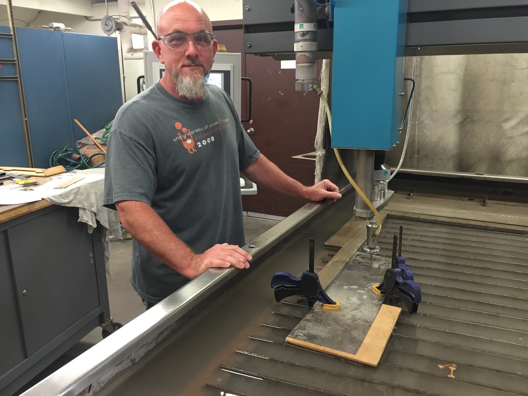
Thanks Butch, for you help with waterjet
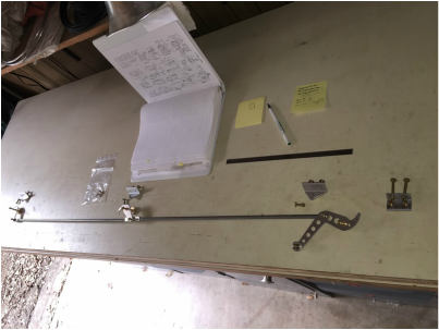
Latch assembly laid out on bench
|
|
Step 8: Firewall to Spar Finish Out (last part of "Installing the Turtleback"):
I progressed to this Step from Ch 14 Step 10 as a part of preparing to do Ch 21 Strakes by getting the spar permanently attached and finished. Once done with the 5 BID layups between spar and longerons, I floxed the side firewall pieces and the Clark foam piece per plans and covered with 1BID layup as shown in the figure to the right with my pressure applying apparatus... Step 9: Upper engine Mount Reinforcements Just following the plans here: 5 BID on the outside and 8 BID on the inside. Since these layups have some complex curvature and bend around the firewall edge to turtleback I rounded the outside edge of the wooden part and pre-wet only 2 BID at a time to allow me to work them in by hand (with gloves) carefully in these curves. On the 8 ply interior layup, the plans are not specific on how to cut the glass and there's been several recommended methods for getting this thick layup to position well in the interior corner. Here's what I did: I wanted the layup to sit flush against all walls without any fibers being smashed or distorted/folded. I also didn't want a seam left on any of the 3 corner edges as has been noted in builder traffic. So I used a pattern that would allow alternating overlap of the portion bending from the turtleback and the spar onto the firewall. I show a picture of this pattern both in it's corner configuration and flat. I did a dry test of this first with single BID to confirm it would lay right, and found that I wanted to cut a little relief for deep in the corner to prevent bunching up in that area. This meant that all 3 corner edges got a full 8 BID uninterrupted fiber cover plies. The only minor downside was that it resulted in 16 plies of flat layup on the firewall face instead of 8. As I applied the 4 x 2 wet plies they alternated the seam from the spar/firewall to the turtleback/firewall so never were there more than 2 plies with the seam in the same place. This section was finished up by flowing on the 2" Al interior engine mount block and associated 1 BID cover per plans. I used plastic sandbags to keep good pressure on the cover while it cured. Insert finished picture of 8 ply interior layup with the engine mount backing block installed. NOW it's time to start on the Strakes in Ch 21... (I'm not skipping forward, this was a return backward, if you've been following the thread of my build process). |
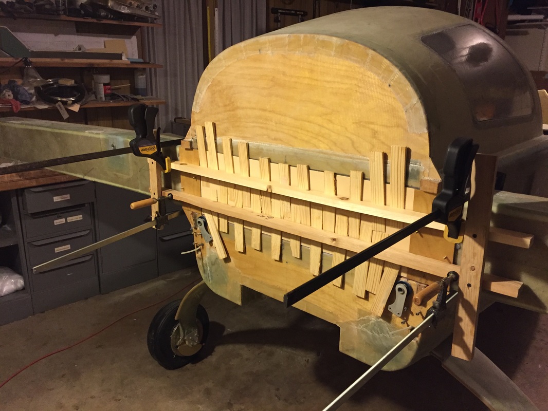
Applying pressure to the Clark foam (with wedges) while squeezing directly on the side firewall pieces.
Outside upper engine mount reinforcement over the foam taper wedge and peel ply.
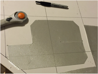
Flat pattern for 8 ply upper interior engine mount layup. Note cut on right side that will be used to bend up and overlap the firewall panels on top of each other.
Same pattern now with the overlap "made" showing how it will lay flush in the interior corner and none of the three corner "edges" have a seam
|