Chapter 26.1: Assembly and Fitting
This covers assorted tasks with getting the Cozy all assembled in the hangar
|
With all components in the hangar I could now get the wings on for good. Uhh, that's a misstatement. I could put the wings on and leave them on a while, before needing to remove them for something else that needed to be done (see later).
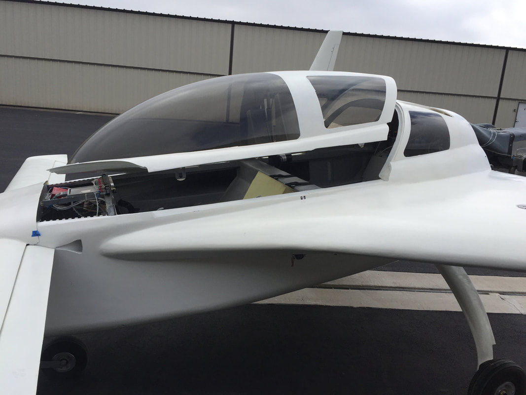
Over the 2018 Christmas holidays I got help from my boys in getting the wings mounted and doing the initial fit check with the cowlings. Pictures to right. Some trimming required on upper cowling/wing interface, but not bad, and lower cowling went right in place, but may need some modification to match lower wing profile AND the upper cowling trailing edge. Update mid January: I have the support tabs now bonded on the upper and lower wing inboard edges and mated with the cowlings. See more detail on cowling completion further below.. 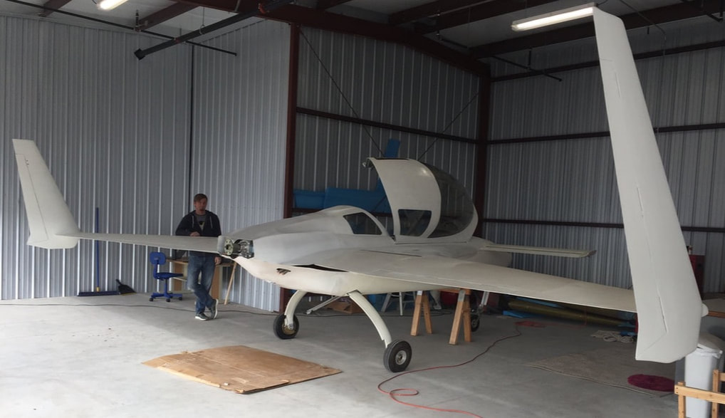
N78CZ starting to look like she wants to fly. In the hangar with wings and cowlings on for the first time!
|
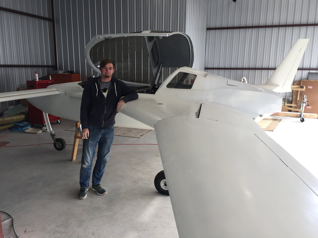
Garrett helped me with the R wing and cowling mounting.
|
|
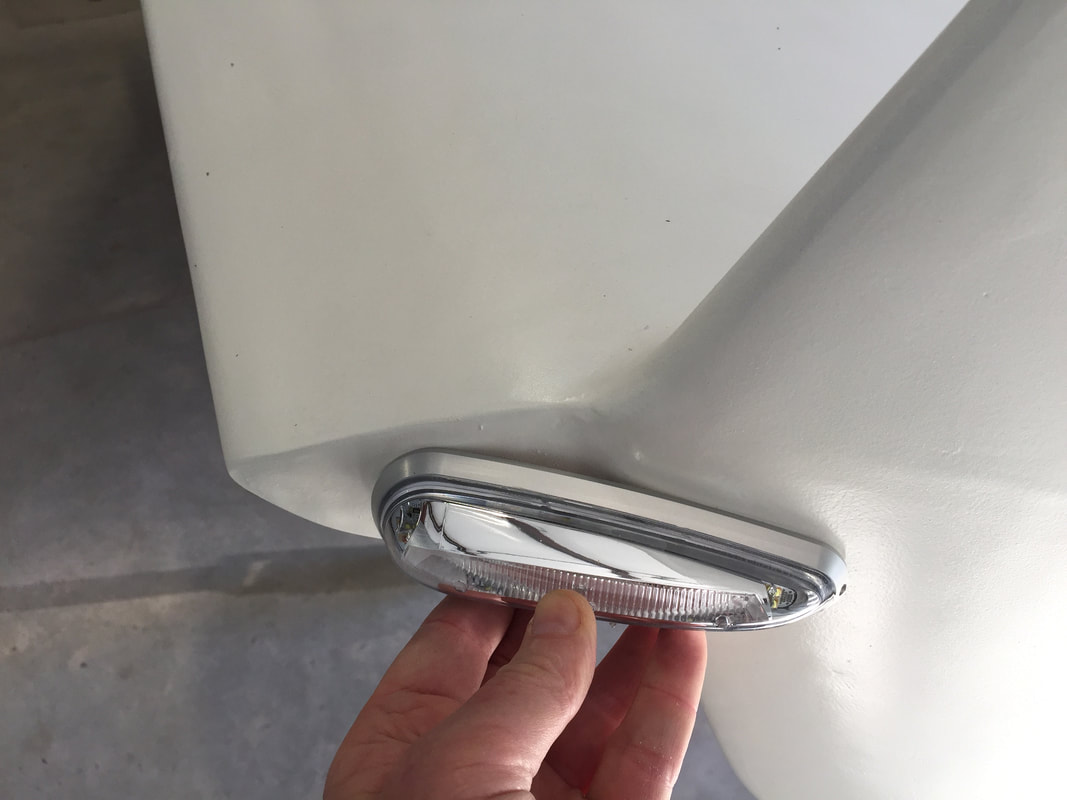
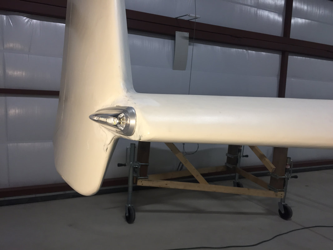
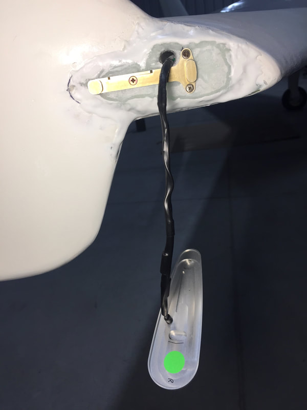
Nav/Strobe Lighting:
Needed to build up the wing-tip with flox to provide good thickness to bolt the Nav/Strobe bracket's to. The lights attach to these brackets. I'm using the AeroLED's, which were expensive but very low drag and current draw. I ran the green synch wire between the wingtips through the spar to keep it out of the engine compartment. I used some tricks here to guide the wires and avoid damage to Comm antenna coax that's in this same wingtip region. contact me for details... Testing shows all the lights working great. At some point I'll do some more cosmetic smoothing around these lights, but they are good for airworthiness inspection now. |
|
|
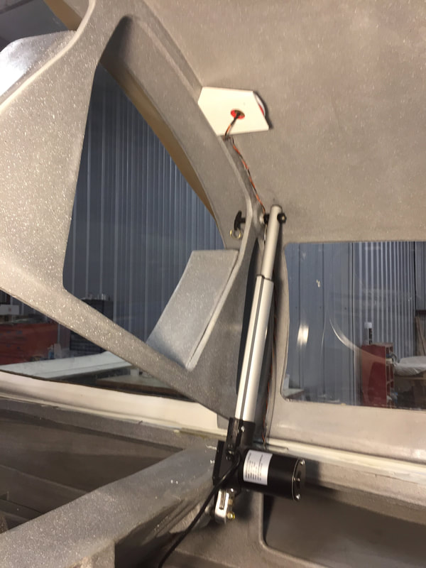
Pitch Trim:
When I got everything assembled in the hangar, I found an interference between the elevator inboard counter-weight and the Vance pitch trim system I'd build a few years ago to his specs. The problem was the location I'd picked for anchoring the actuator to F22 and would require movement of about 1/2". I'm not sure how I didn't find this before, but part of the reason is that I kept the pitch trim actuator safely stored in a cabinet after I'd done the initial proof that it ran, without connecting it to the elevator push rods coming from the joystick. I should have completely connected everything, but was doing too many things at the time... Lesson: finish things. I'd opened up the hole in the IP a little to enable the trim actuator spring housing to come through in addition to the push rod on the pilot side, but it now looked like needed more clearance here, and I was growing uncomfortable with the smoothness of the actuator motor, which had been sitting for a couple of years. In the mean time, there was significant debate on the list associated with a failure mode in this pitch trim system that might prevent recovery from an uncontrolled full extension of the actuator. Many have been flying with this system for many hours, and I wasn't originally thinking of changing, but after some internal debate, I started pursuit of the Davenport spring approach which would shift the whole pitch trim to the centerline area behind the IP. I got a lot of help from Rick Hall, who'd been through about 4 iterations optimizing the spring recently for his Cozy MKIV. Since work was taking me up near where Rick flies, he loaned me the jigs for making a spring and even made an initial one to his current configuration for me to try. Thanks so much Rick! My implementation shown below. 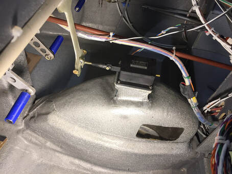
Ray Allen servo connected to Davenport spring for pitch trim. All wired up to hat switch (not visible in this view) on the center console just fwd of the throttle lever.
|
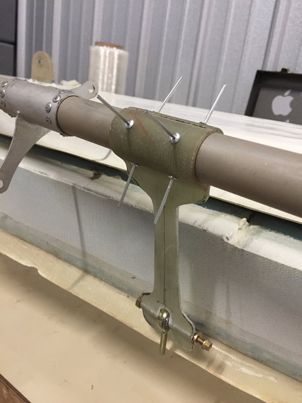
Davenport spring prior to epoxy bonding to elevator torque tube (showing the 8x1/8" rivet positions) later flox bond the spring to tube and pop the rivets.
Glassing the actuator bracket to the nose wheel cover (surface sanded down to bare glass prior). Edges will be trimmed and everything painted later. Wrench on top is just weighting the whole thing down for good bond.
|
|
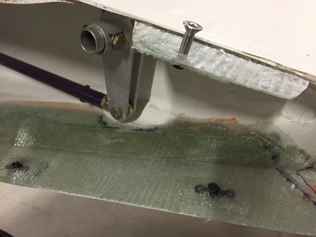
Roll Trim:
This couldn't be installed until the wings were on as it depends on having the full control linkage in place. I'd built the Hanka spring back in Ch 17 (Trim), and procured and wired the Actuonix linear actuator in Ch 22 (Electrical). Here, I needed to get the mounting bracket built and attached to the firewall and complete the connection point to the control rod as shown in the figure. It's a really simple system, but required custom bracket build and I didn't use a real fancy connection between the spring and the actuator. If interested in the details, contact me directly. |
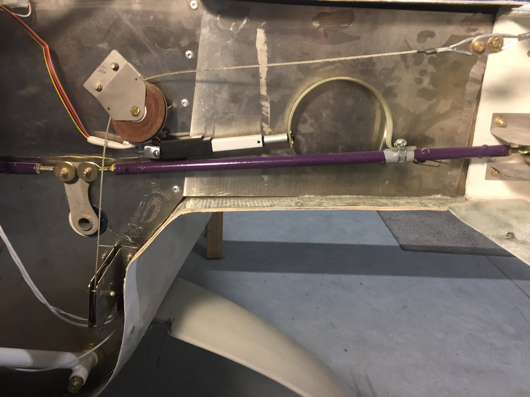
Installed and tested. Works great, with full control authority at any time and easy motion.
|
|
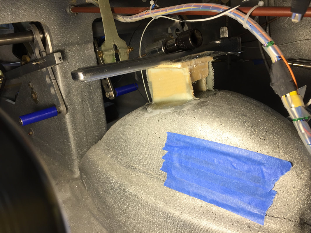
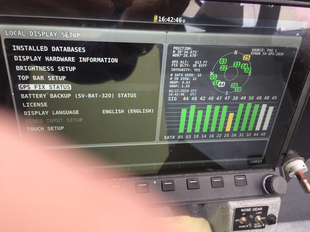
GPS Antenna in TB:
I chose to put the Dynon GPS 2020 up in the Turtleback just behind the bulkhead that the headrests are mounted to. This would get the antenna up high and away from everything else for what I hope will be great satellite reception. It works great in tests just outside the hangar, and we'll see for sure once flying. To mount it there, I built a plastic bracket for it and used 2 plastic screws into the bulkhead, which I locally filled with flox as hard points. It's nice and light, so the loads should not be great. I ran the cables from here down the co-pilot side of the TB bulkhead, down the back of the co-pilot seat back, and then forward through the co-pilot arm rest to the IP/HDX unit. Once I'd confirmed it worked I put a MOLEX connector in at the canopy/longeron interface, so it's easy to disconnect when I need to remove the canopy. Later note: Greg Cross found that he had significant satellite signal reduction mounting same GPS antenna below the IP cover. I checked the satellite strength with my antenna position and it looks great. Remember that I'm between two rows of hangars here so some of the lower satellites are not blocked.
|
The MOLEX connector for removing the canopy and wiring behind the co-pilot seat.
|
|
Completing the Cowling Installation:
I could not finish the custom cowlings (started in the garage) until I could be in the hangar and have the wings mounted semi-permanently. Ch 23 shows how to build the fiberglass tabs on the inboard ends of the wings (top and bottom) and I used the same anchor nut approach that I'd used for the cowling to firewall/spar tabs. The lower cowling shape as molded did not fit well to the upper cowling at their trailing edges once they were both tightened to the wings AND at the upper and lower interface near cylinders 1 and 2. A little bulge and significant stress in the TE was induced when I tried to force good TE fitting. To eliminate the bulge and have a nice fit, I needed to cut the lower cowling along a line about 18 inches where it's wing profile changed to the engine profile. I could then build the TE tab that folds at the upper cowling/lower cowling TE and will have anchor nuts for the lower cowling attachment. Once that tab is completed and attached, I repaired the cut area with 3 BID on the inside and 1 BID on the outside. 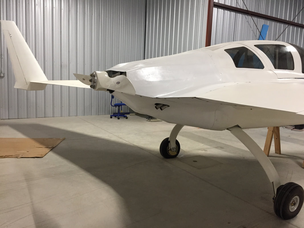
Finished cowlings. They fit well now and should work fine for the time being. At some point in the future (before I final paint), I may do a version 2 on the cowlings with improved shape and lighter weight, but we'll see...
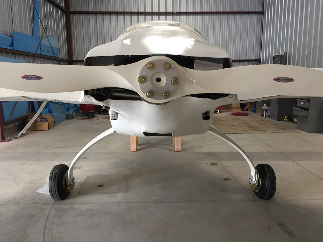
The view of cowlings from the back. They are not perfectly symmetric, but accomodate the cylinder banks on the the right side being slightly more forward than those on the left (all flat configured engines have this attribute).
|
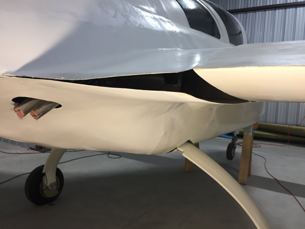
Here's a look at the mismatch between the lower cowl and the wing and upper cowl. Fix was to cut a slit about 18" long from the inboard aft corner to the left in the lower cowl. This allowed the lower cowl to be fit at both interfaces simultaneously with no stress. Once attached to the wing, the 18" cut was then repaired with 3 BID.
Tabs and anchor nuts on the inboard edges of wings for cowling interface.
A look at the repair for the 18" slit on the inside of the cowling (green area). Not pretty, but also not visible once upper cowling is installed. :-(
|
|
Non-Dynon Skyview - Warning Lights:
Now that the Cozy is assembled and the electrical system is consistently being operated in the hangar, I'm returning to complete the circuitry needed to feed my IP warning lights. I'm realizing that I could have done this while the fuselage was still at home, but that's the way it goes. It will just take longer to complete with the commute. I'll document more on this when it's done, but for now, I'll just explain the planned end state. Because I'm using the VP-X solid state power distribution box in my Cozy and it's linked to my Skyview EFIS, MOST electrical problems will be sensed and alerted through Skyview display directly, and in most cases, faults can be cleared from the EFIS with a couple of button presses. This task deals with the primary pilot error elements that I want a separate notification on, or possibly/ eventually an automated reaction to. For Phase I this will just be warning lights, and response will be pilot action. I have 3 warning lights (red LED's) in the IP right above the EFIS that are separate from the installed equipment (EFIS/Radio/etc) as described below. All require Master Switch to be ON: - Canopy: "ON" when the canopy lock micro-switch is open AND ECU is "ON" and throttle is greater than 30%. - Gear: "ON" when the landing gear is NOT fully extended AND the AGL is between 3 and 120 meters. I'm using the same laser altimeter that Marc Zeitlin uses for his nose gear auto-extend circuit. I'm postponing this functionality for now until I have more experience with the Altimeter. I will however use the audible warning from Dynon EFIS into my headset: IF gear not fully extended and airspeed <90kts OR if gear extended and airspeed >100kts. - Brake: "ON" when the speed brake is not fully retracted AND the throttle is greater than 30%. This is a reminder to retract the brake when not wanted (typically for a go-around, or if I've had it down while taxiing to takeoff position). One additional ECU Warning LED is located in the panel to the left, and is a direct feed from the UL Power ECU that indicates a problem with the engine/or it's controls (if I can't already hear or feel it). 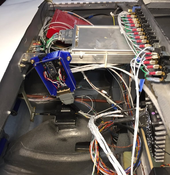
Arduino shield mounted behind the Instrument Panel and D-sub25 connected.
|
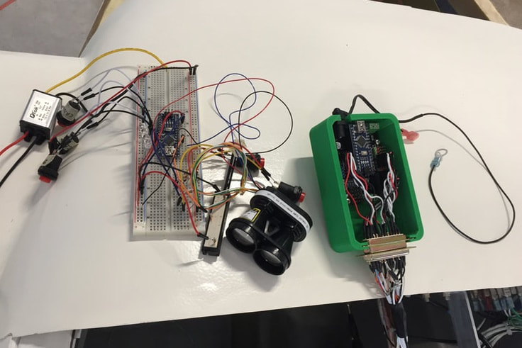
Breadboard implementation ON THE LEFT. This is what I used to develop the Arduino software. The little box with the yellow wire is 12V-5V converter to mimic the power supply in the Arduino shield. I used simple push buttons to mimic the micro switches, a linear variable resistor to mimic the potentiometer on the throttle, and the actual laser altimeter that looks like a mini binocular. ON THE RIGHT is a prototype green box I designed to hold the Arduino shield, with access for the power cord, USB, and integrated holder for the D-sub25 connector. There's also a cooling vent.
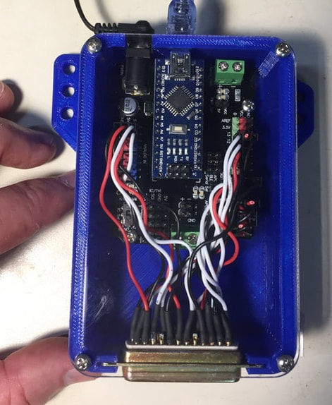
Here's the final 3D Printed Arduino shield box with an acrylic cover that was laser cut from the CAD. The specific Arduino shield I'm using is a DFRobot DFR0012 board.
I am not depending on these lights completely for safety, they are just an add-on alert. If this system for any reason isn't working right in flight, I can turn the whole system off or re-set it from the Instrument Panel.
|
Engine Exhaust Side Heat Shields:
As I finalized the cowling and had more time to examine the fit with the engine and the exhaust, I needed to deal with shielding the cowling from both convective and radiative heat from the exhaust pipes. These pipes are short, but they will be quite hot. I also want to insure that the cylinder cooling air gets well diverted out back towards the propeller and not swirling around in the engine compartment. To aid in directing the flow aft and shielding radiation exposure from the aileron controls I designed, built and installed custom 6061 aluminum side shields that could attach with 2 of the same bolts used to secure the cooling plenums on either side. A couple of sample pictures are shown below (before/after) without the lower cowling installed. I may use the rubber sealing material typically seen on the upper forward baffling with a Lycoming to reduce leakage of high temp air in the forward/side areas of the engine compartment.
As I finalized the cowling and had more time to examine the fit with the engine and the exhaust, I needed to deal with shielding the cowling from both convective and radiative heat from the exhaust pipes. These pipes are short, but they will be quite hot. I also want to insure that the cylinder cooling air gets well diverted out back towards the propeller and not swirling around in the engine compartment. To aid in directing the flow aft and shielding radiation exposure from the aileron controls I designed, built and installed custom 6061 aluminum side shields that could attach with 2 of the same bolts used to secure the cooling plenums on either side. A couple of sample pictures are shown below (before/after) without the lower cowling installed. I may use the rubber sealing material typically seen on the upper forward baffling with a Lycoming to reduce leakage of high temp air in the forward/side areas of the engine compartment.
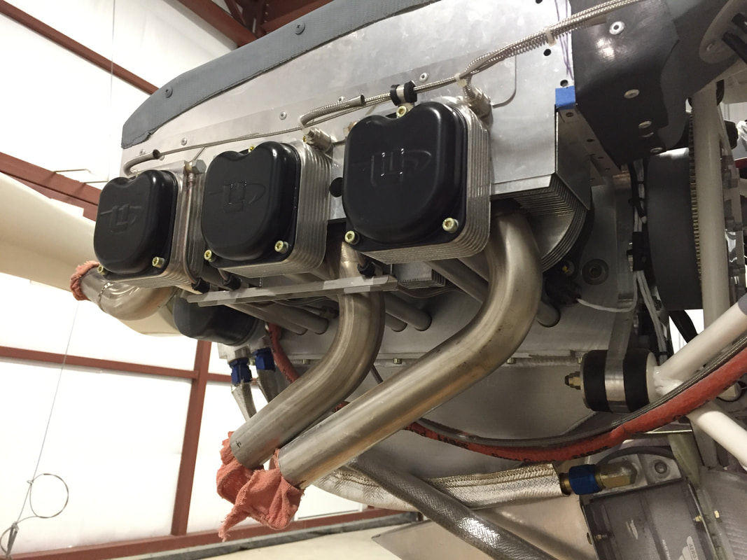
Cyl 2-4-6 side before side shield install
|
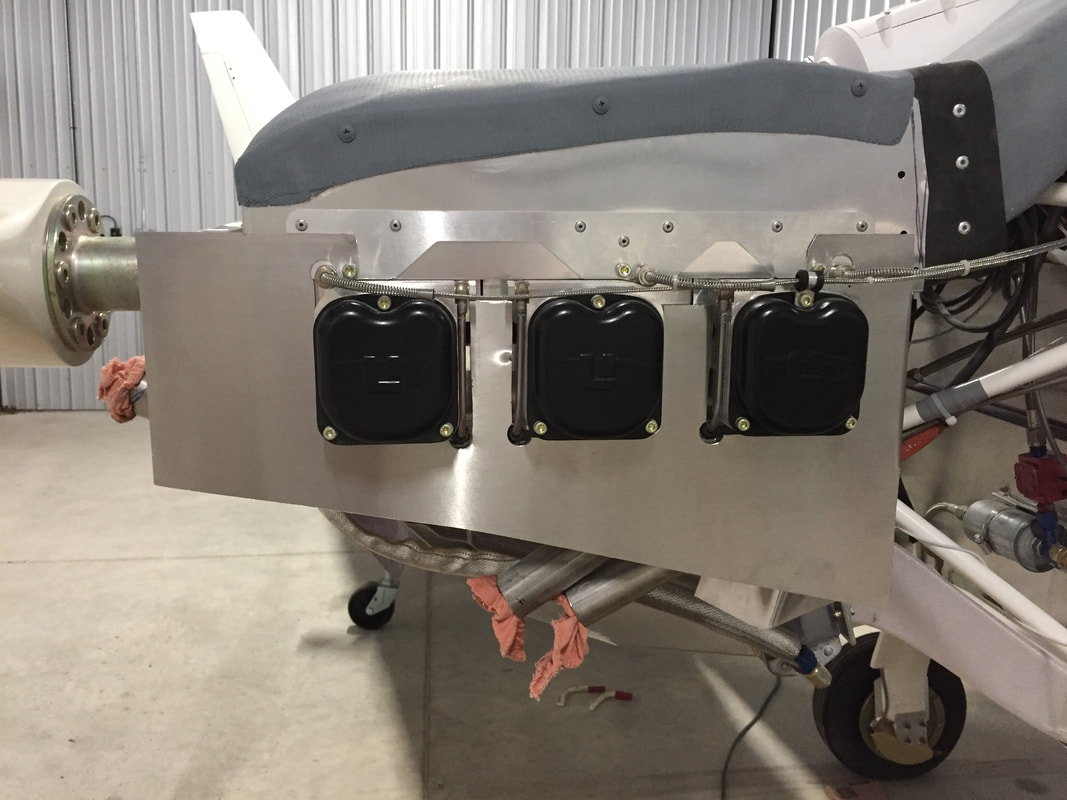
Side shield in place, before rubber seal on lower edge.
|
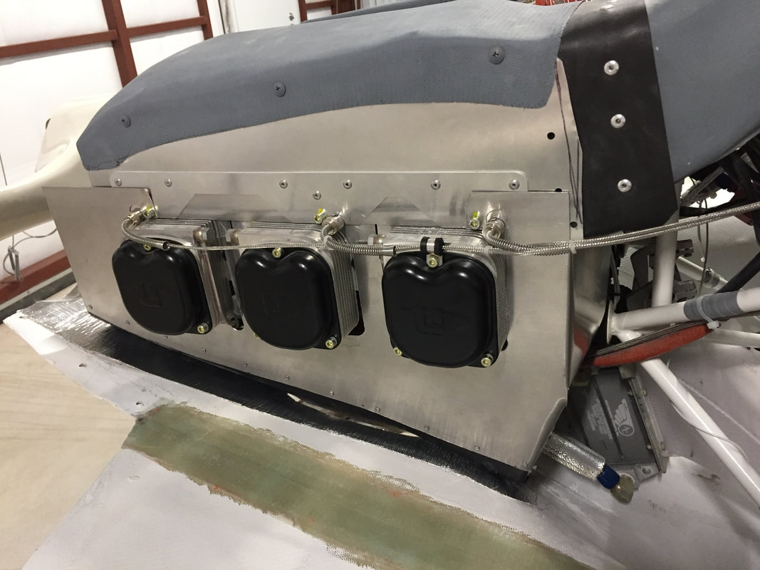
Side shield with rubber seal against lower cowling and foil heat shield applied to lower cowling as well.
|
View fro propeller area of cowling foil heat shield and side shield near #2 cylinder exhaust.
|
|
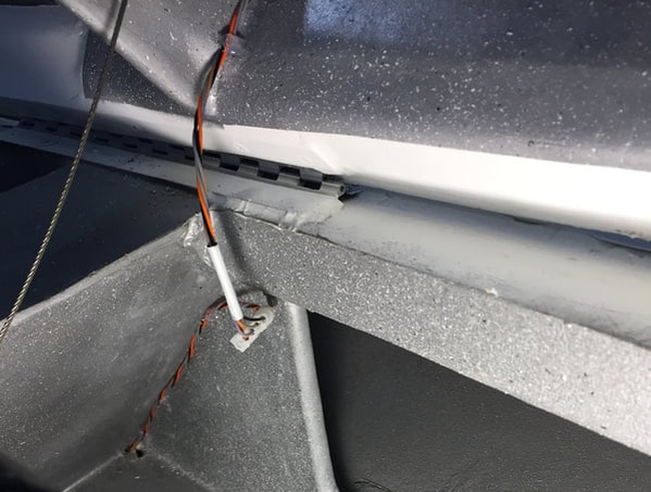
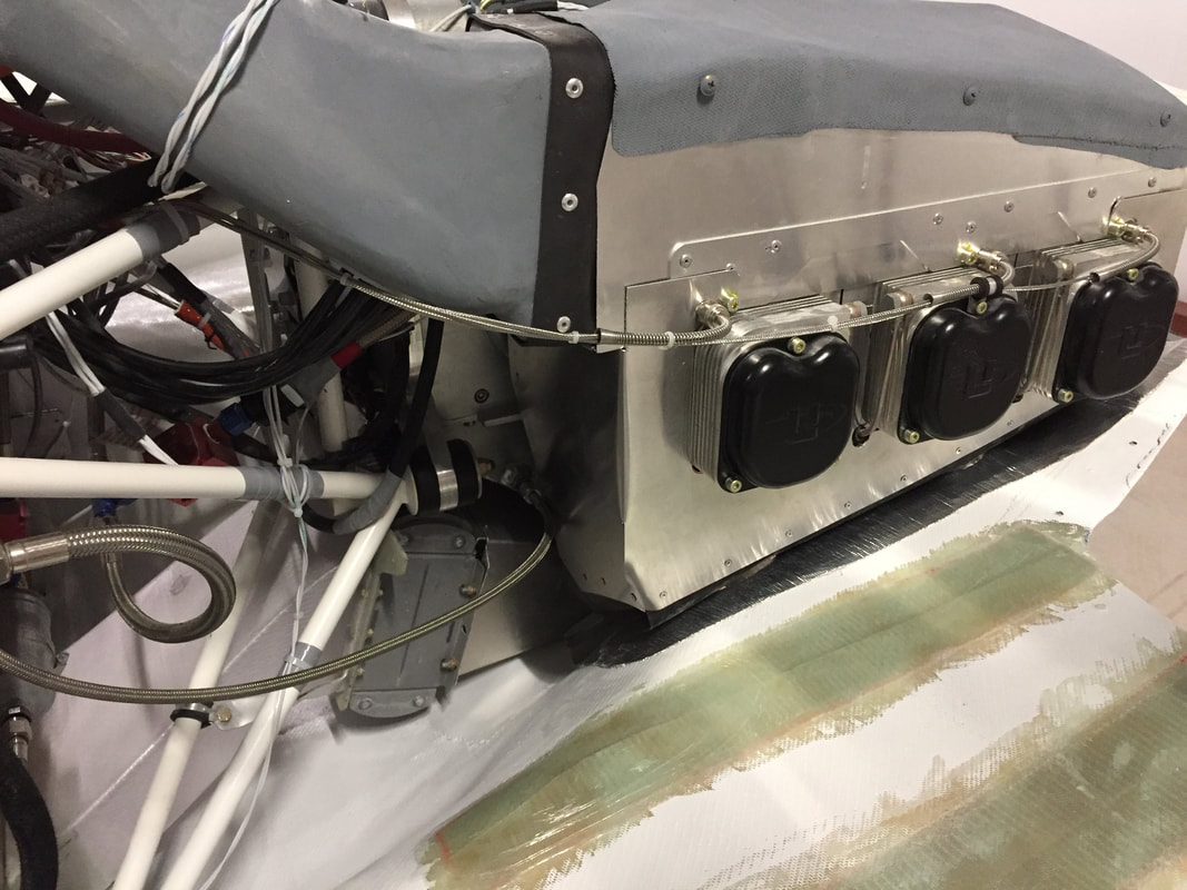
Thermocouples:
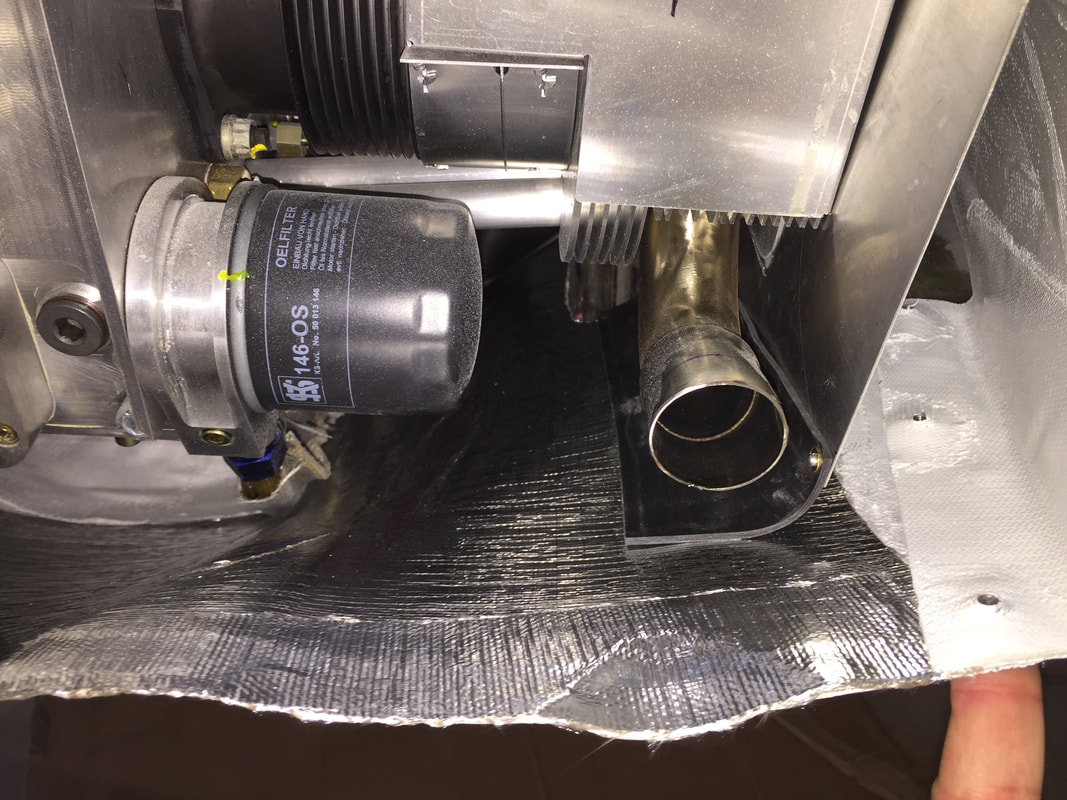
My UL520is engine has a fully computer controlled electronic ignition and fuel injection system, so there is no utility in adding exhaust gas temperature (EGT) monitoring. The Dynon Engine Monitoring System (EMS) has provision for measuring up to 6 cylinder head temperatures (which I use) and 6 EGT's. I chose to use this EGT monitoring capacity to monitor some other temperatures that may be important as I get to know the Cozy under various flight and ground conditions. I bought K-type thermocouples, which are what the EGT's are, and wired them into the EMC and they are interpreted fine. In the Dynon HDX I simply had to assign the measurements a name (other than EGT's) and give them a place in the display when I want to monitor them. Of note: the thermocouple wire size was too small to wick solder into the 25 pin connector, so I had to use short lengths of 20 ga wire between the thermocouple wire and the actual EMS connector. The temperatures I'm monitoring are: - Left brake (for overheating on heaving braking conditions) - just monitoring one side on assumption that they are roughly even - engine compartment in the upper area where most of the wiring is (between engine and firewall) - Rectifier for the engine alternator (it's air cooled, and I'd like to insure it's getting adequate flow) - Master solenoid - I've been told this can get pretty warm, and by monitoring it over time, I hope to be able to detect degradation before failure. I'll get some pictures of this when completed (have tested one complete circuit already). |
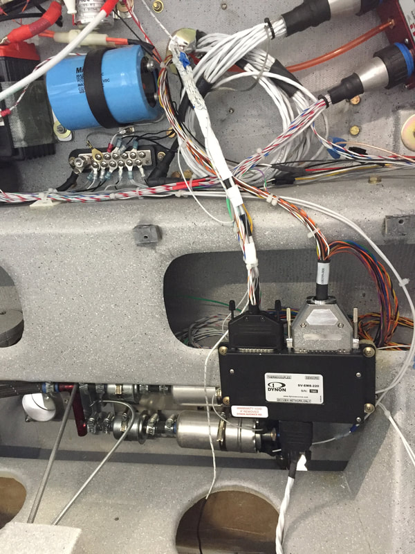
Thermocouples are all integrated into the black D-sub connector on the LEFT side of the Dynon EMS box. The wire coming up through the round hole in the main gear cover comes from the left brake.
|
|
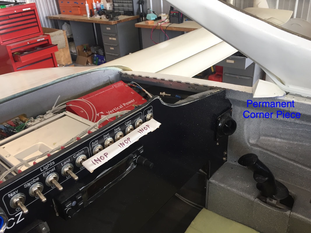
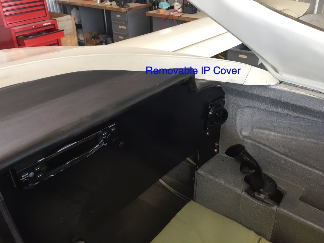
Instrument Panel mod to allow removal without removing the Canopy:
Being able to remove the instrument panel cover is really important when checking electrical functionality and doing the final installation of things like the ELT and trim system and the Autopilot, which I'll cover later. I find that most of the time in the hangar I still have this cover off. However, I like having the canopy installed and being able to close it down and lock the plane. In the plans the IP cover is made in 2 parts and only the small portion that's inside the canopy is easy to remove, but I didn't like having a seam that could leak in this area above the instruments and behind the IP, and built the IP cover in one piece (others have done this too. This piece is installed by slipping under the canard cover trailing edge and locking in place with the piano hinge pins as shown back in Ch 18 step 17 (shown on the Ch18.3 page). The problem is that with a side hinge canopy the fit is too close between the IP cover and the canopy (even with the canopy completely open) on the hinge side to allow slipping the IP cover in place under the lip of the canard cover. To remedy this problem I made an angled cut in the aft section on the IP cover that would allow the portion that can't be cleared with the canopy to remain in place all the time bonded to the longhorn, while allowing the rest of the IP cover to be slid up and back without hitting the canopy, when the piano hinge pins are removed. I'll get a picture of this modification in here soon. Eventually I'll seal this cut line from the outside to prevent water leakage, but it's well away from the electronics. |
|
See page added called 26.2 for more hangar related work...