Fish's Cozy MKIV
  • Welcome
  • Preparation, Visits, Tips
    • Preparation
    • Visits
    • Tips and Tricks
    • Special Cases - Interesting Fixes
  • Chapters 3-15
    • Ch 3 Practice
    • Ch 4-7 Fuselage, Main Gear
    • Ch 8 Head Rest, Heat Duct, Seat Belts
    • Ch 9 Main Landing Gear
    • Ch 10-12 Canard & Elevators
    • Ch 13 Nose >
      • Ch 13.1 Nose gear, Brakes, Landing Light and Skid Plate
      • Ch 13.2 Nose Top & Canard Cover
      • Ch 13.3 Relevant Later Work
    • Ch 14 Spar
    • Ch 15 Firewall
  • Chapters 16-25
    • Ch 16 Controls
    • Ch 17 Trim
    • Ch 18 Turtleback/Canopy >
      • Ch 18.1 Turtleback
      • Ch 18.2 Canopy
      • Ch 18.3: Latch, IP Cover, Misc
      • Ch 18.4 Lift and Locking Canopy (Version 1)
      • Ch 18.5 Electric Lift Canopy (Version 2)
      • Ch 18.6 NACA's for Engine Cooling
    • Ch 19 Wings
    • Ch 20: Winglets/Rudders >
      • Ch 20.1 Winglet Fabrication
      • Ch 20.2 Winglet Attachment
      • Ch 20.3: Rudder Fabrication
    • Ch 21 Strakes >
      • Ch 21.1 Strakes: Through "Top Hats"
      • Ch 21.2 Strakes: Bottom Skin through Prep for Top Skin Final Bonding
      • Ch 21.3 Strakes: Top Skin Final Bond through Fuel Tank Seal
      • Ch 21.4 Strakes: Misc Completion of Strakes
      • Ch 21.5: Strakes: Wing/Strake Fit Check
      • Ch 21.6: Strakes: Post Cure Tanks
    • Ch 22: Electrical >
      • Ch 22.1: Electrical: Inst Panel
      • Ch 22.2: Electrical: Firewall
      • Ch 22.3: Electrical: Warning Lights
      • Ch 22.4: Phase I Testing
    • Ch 23 Engine and Cowling >
      • Ch 23.1 Firewall and Mount
      • Ch 23.2: UL 520is Initial Integration
      • Ch 23.3 Cowling
      • Ch 23.4 UL 520is First Start
    • Ch 24: Seats, Armrests, Fairings >
      • Ch 24.1: Fairings
    • Ch 25: Finishing >
      • Ch 25.1 Canard
      • Ch 25.2 Interior
      • Ch 25.3 Fuselage/Strakes Bottom
      • Ch 25.4 Fuselage/Strakes/Canopy Top
      • Ch 25.5 Wings
      • Ch 25.6 Assembly in Primer and W&B 1
  • Ch 26: Hangar
    • Ch 26.1 Assembly and Fitting
    • Ch 26.2 More Punch List Stuff
    • Ch 26.3 Inspections
  • Ch 27: Ground Tests, First Flight and Ph I Testing
    • Ch 27.1: More Ph I Testing Stuff
  • Ch 28: Post Phase I Improvements
  • Ch 28.1: More Improvements
  • Ch 29: IFR

Ch 18.6   NACA's for Engine Cooling


Cutting and shaping the NACA Scoops in the aft (fixed) portion of the TB after deciding to use the UL520is Engine:
​     This modification was done more than a year later than the TB build, when I decided to use the UL520is engine, instead of the standard Lycoming 360.  See the engine pages on other integration activities.
​     I'll fill this out more when I get time...I'm having trouble finding pictures of this cutout and shaping process in my archive of stuff, and it's probably because it was done way out of order, and also because I may not have remembered to take some...
Picture
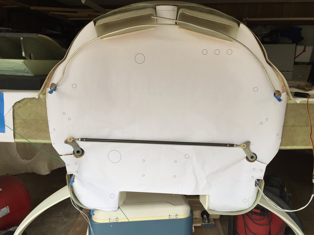
One photo I found was after completing the upper NACA's and you can see the air feed throughs here as I'm templating the stainless steel firewall sheet with a CAD generated paper pattern.

In Phase I testing, I found the need to install small vortex generators ahead of these scoops to enable effective capturing of air at high speeds and in descents.  Here's a link to the page describing the installation of these VG's.
Proudly powered by Weebly