Chapter 16 Controls
|
|
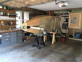 Fuselage on side to start Controls work.
I purchased all the recommended parts for Ch 16 and 17 from both ACS and Cozy Girls and will buy the tubing (Schedule B, minus CS 105, CS 106, CS112 and CS122 locally to avoid the shipping costs. The CS parts listed in previous were included in the Cozy Girls parts with the joystick assembly and rear bellhorns.
The first thing I needed to do was get the fuselage into a position where I can work on it. Following the recommendations of others I turned it on it's side to provide easy access to the interior. It's light enough for me and my son to lift while my wife helped rotate it by lifting one of the main wheels. The steel gas can is empty under the wheel and there are wood spacers between it and the wheel/tire to be soft and level the fuselage side on the saw horse. Likewise I folded towels on the saw horses to soften and stabilize the interface with the fuselage side.
The first thing I needed to do was get the fuselage into a position where I can work on it. Following the recommendations of others I turned it on it's side to provide easy access to the interior. It's light enough for me and my son to lift while my wife helped rotate it by lifting one of the main wheels. The steel gas can is empty under the wheel and there are wood spacers between it and the wheel/tire to be soft and level the fuselage side on the saw horse. Likewise I folded towels on the saw horses to soften and stabilize the interface with the fuselage side.
Steps 3 and 4: Installation of Pitch and Roll System
|
I'm still working in this area but want to get some notes of potential relevance to other builders:
a) Parts: If you order parts for Ch 16 and 17 from Cozy Girls (CG), take the time to figure out the overlaps with parts in ACS. The CG parts cost more but they saved me some fab time. I also noticed that ACS doesn't list the needed rivets (AN470 AD4-10) that you will need to secure the CS 1 inserts that are threaded to accept the Aurora bearings. I bought the CS 1's from CG but still needed to go back and get the rivets from ACS later to finish. I ordered joystick torque tubes and most of the other parts available from CG Products for this section. They do really good machine work and I was inexperienced with the metals treatment like Alodine (Aluminum) and Cadmium plating (steel) that they do. If you are planning on using parts from them, place your order early. If they have the parts in stock, it's very quick turn around, but they subcontract the coating stuff and for economic reasons need to do some in large batches. I caught them when they were out of joystick torque tubes and 6 week wait turned into 4 months. I still really like their parts, they are top quality and I can't make them myself as inexpensively, but they are still a small business, so be prepared to go with the flow or make parts yourself if they don't have what you need in stock (I do this some too). Thank goodness they are providing this service to our building community... OK, the build: Really the controls torque tubes are not that complicated, and it's made really simple if you buy the prefab bearings (CS 108&117) and connecting tubes (CS115) and control stick (CZSA) and firewall bell crank (MKCS124) and the torque tube assembly (CS105 pre-fitted with CS106 and CS112 insert). Just follow the drawings in Ch 16. Get everything assembled before glassing the bearing bulkheads in place. There's no exact measurement given for the forward location, but you can get pretty reasonable estimates from looking at the M Drawing for the cockpit, same for the rear bulkhead. I installed my tubes with the fuselage on it's side (one side at a time, so that gravity would keep everything still, and it really makes it so much easier to work on the inside with it tipped up like this. There's an added benefit to this in my work space because it opens floor space for meed to work on wings with them jigged trailing edge up. I have wings from David Pierce because he jumped ahead to Ch19 before completing Ch 13 or starting Ch 15, 16, 17, 18. I've put a few pictures from the Right side controls install here for reference. |
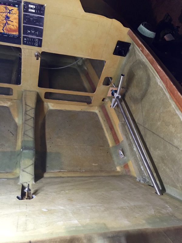
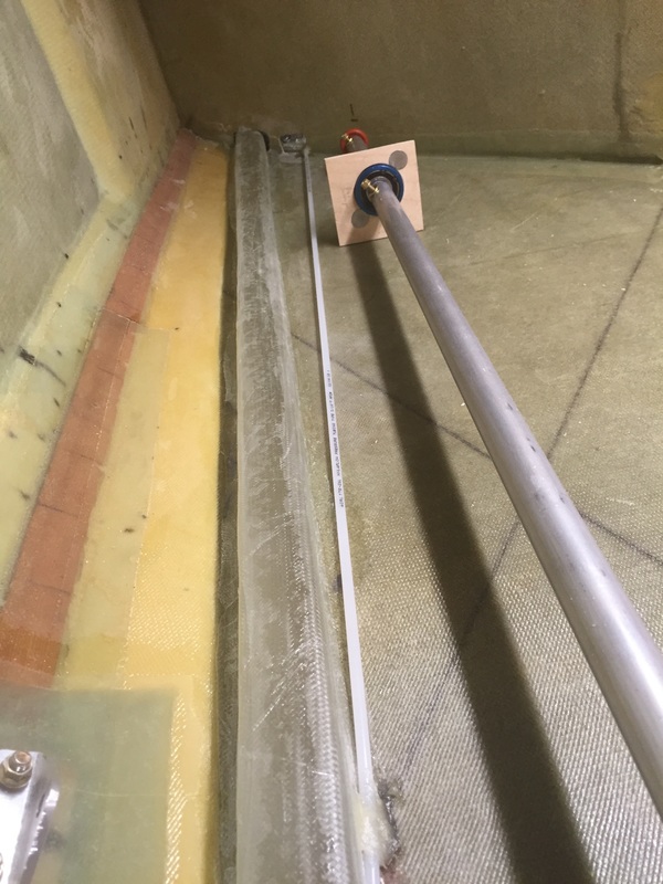
Joystick torque tube finally arrived allowing me to assemble all of the tube based controls in the fuselage. Already dreaming about filling in the Instrument panel... paper now.
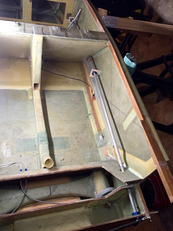
Another view of full length of control tube back to firewall. These photos are rotated 90 degree's counter clockwise: the green towel and saw horses that the fuselage is resting on it's side for easy access (highly recommended)
|
Connecting Pitch Control to Elevators
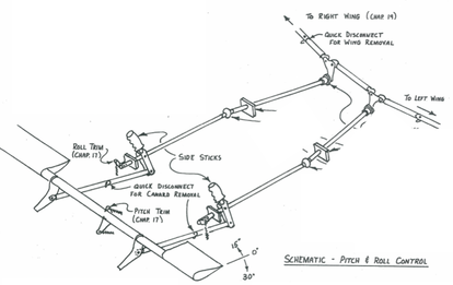
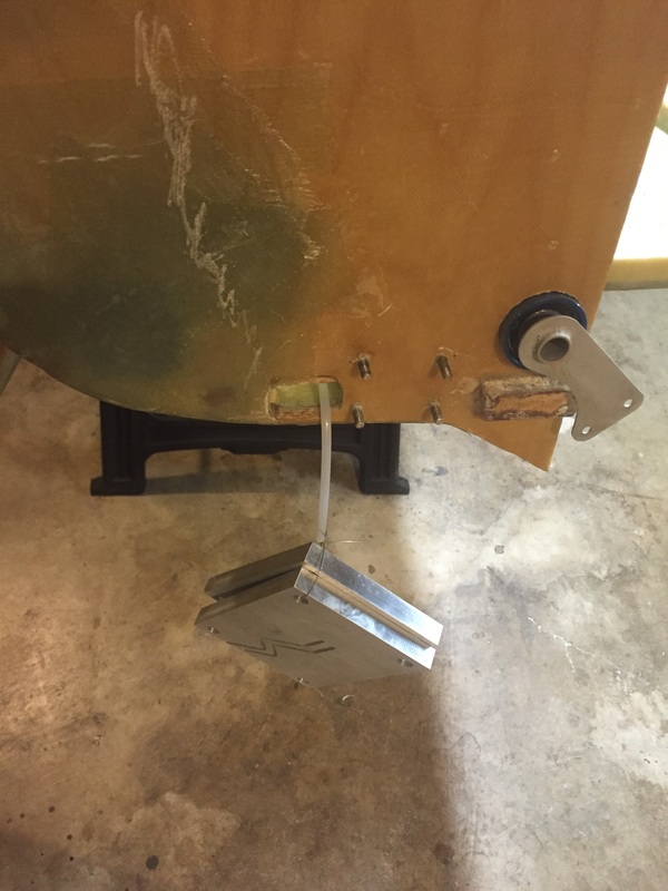
After I'd gotten the arm rests in (See Ch 24) and had the fuselage back upright, I made the connections between the joystick and the elevator torque tube for pitch control. I'd made all the tubular pieces with Aurora ball joints when making all the Ch 16 tubular pieces but this elevator connection requires a "fit" with the canard mounted to know where to cut for the quick disconnect pin shown in the plans at the bottom left of page 3 (it's also labeled Quick Disconnect in the schematic at the top of this web page). Here's a short clip of my Co-Pilot performing the first tests of the elevator control from the cockpit...
After I'd gotten the arm rests in (See Ch 24) and had the fuselage back upright, I made the connections between the joystick and the elevator torque tube for pitch control. I'd made all the tubular pieces with Aurora ball joints when making all the Ch 16 tubular pieces but this elevator connection requires a "fit" with the canard mounted to know where to cut for the quick disconnect pin shown in the plans at the bottom left of page 3 (it's also labeled Quick Disconnect in the schematic at the top of this web page). Here's a short clip of my Co-Pilot performing the first tests of the elevator control from the cockpit...
Step 5: Routing and Rigging the Rudder Cables
|
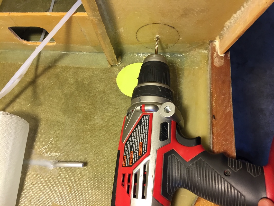
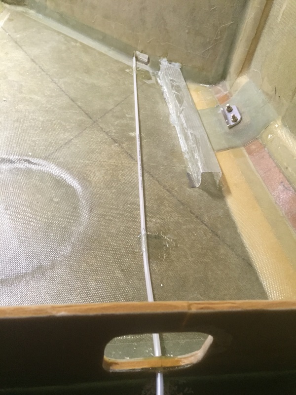
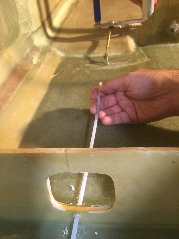
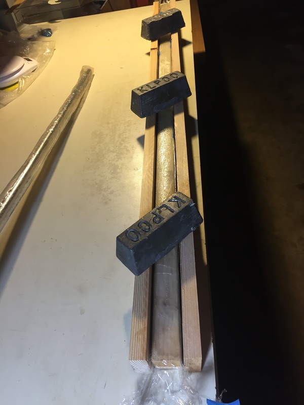
I wanted to keep the rudder cables as straight as possible in the fuselage to reduce their rubbing on the inside of the nylaflo tubing. I lined up the angle from the attachment point at the pedals with the desired place in the forward seat back (about an inch above the top of the electrical conduit (see next paragraph about them). and found where I wanted to pass through the instrument panel. I drilled a 3/16" hole through the instrument panel close to but not on the wall since the cable would be coming from the pedal at an angle towards the wall. This hole provided enough friction fit with the Nylaflo tubing to hold it in place even with a small weight tied to the other end of the tubing sticking out the back of the firewall. With the tubing stretched I could see where it wanted to be straight and minimize disturbance to these lines. the pictures show how this worked out for me (which is slightly different than running the tubing just on top of the electrical conduit. I will not run the actual rudder cable inside this tubing until later when the wings are done. NOTE that all this was done before the Ch 15 Firewall work referenced at the top of this page. The electrical conduit was made with single ply BID wrapped over the plans specified 1-1/8" x 1" wood strip which I checked for straitness. I cut these wood strips from packing material that ACS included with larger foam orders. I used palette wrap around the wood as well as up over the top so that I could weight some extra wood strips on the sides to keep the flanges straight during cure. Once cured I just removed all the plastic pallet wrap and sanded the flanges to allow them to bond to the peel plied sides of the fuselage. I liked the single ply of BID since it has no significant structural load and it allows easier view of wires passing inside. Views of it installed can be seen above where I'm referencing the rudder cable tubing installation. |
Excursion to build the Ventilation Scoops and Ducts
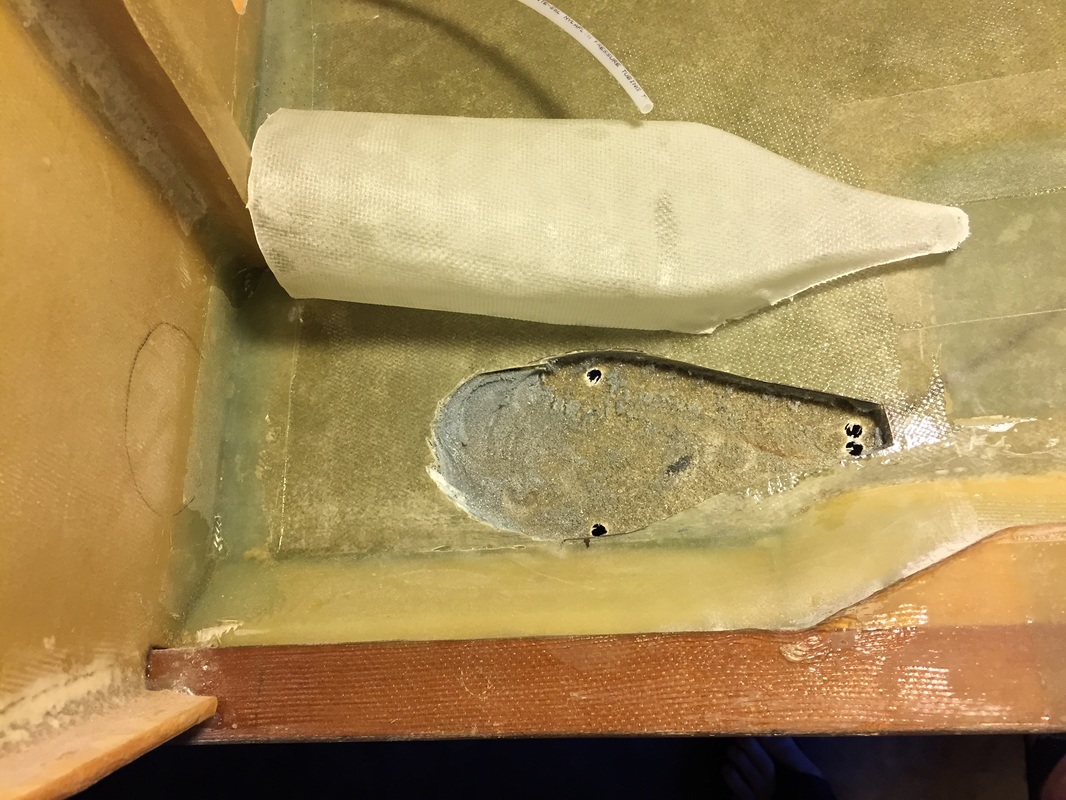
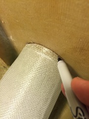
After cutting the inside skin and grinding out the foam for the NACA shape. Note the rounded area aft of the wider spaced twin holes in outer skin: this is clearance for the blended duct shape that tapers from the outer skin to the round opening in the Instrument Panel. This rounded area is NOT cut in the outer skin when the NACA opening is made.
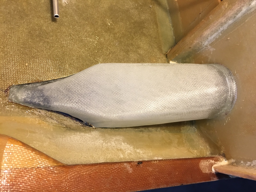
View of the NACA vent/duct glassed to the IP and floxed to the inside of the fuselage outer skin.
|
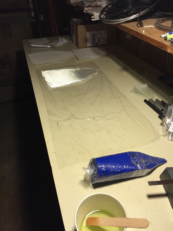
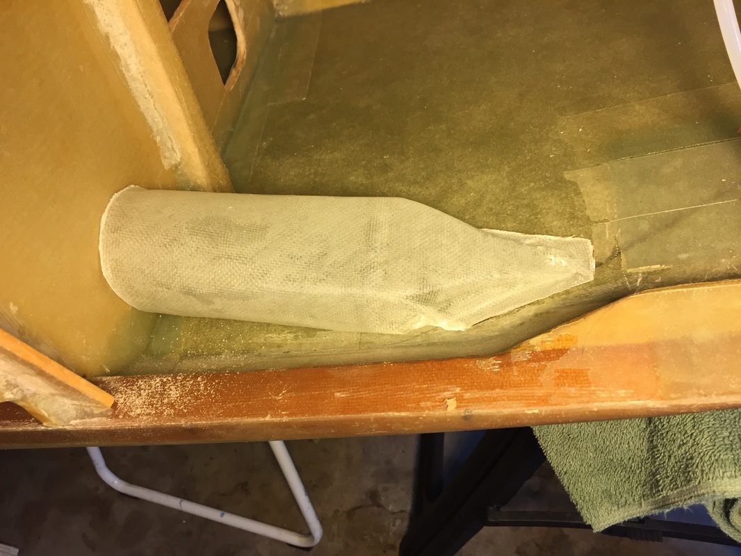
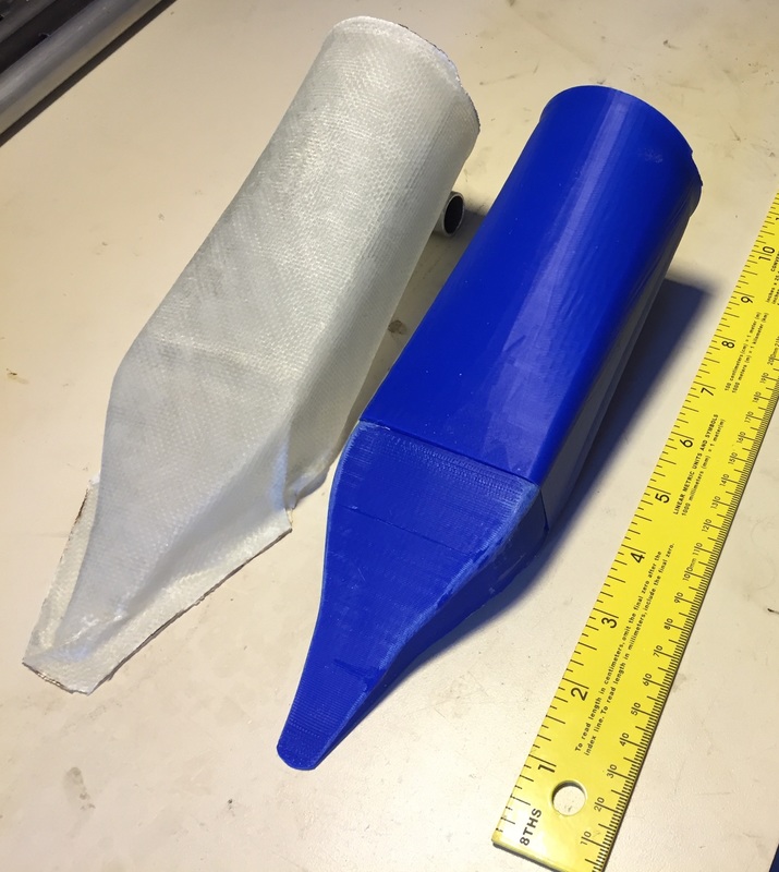
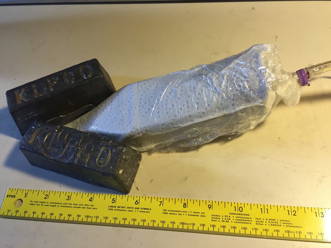
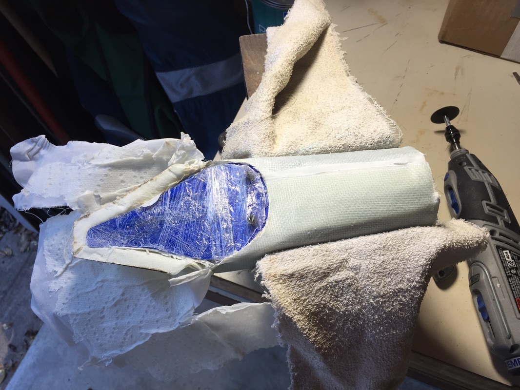
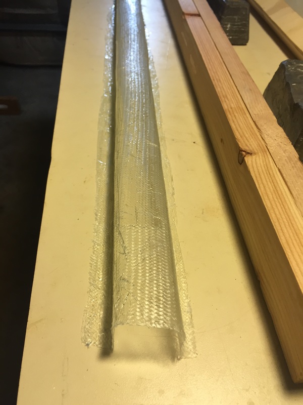
While I was waiting for the forward torque tube assembly to arrive from Cozy Girls, and had the fuselage turned on it's side, I decided to work on creating the NACA scoop and duct for cabin ventilation. I'd looked at these on other Cozy's I'd visited and noted their position relative to the trailing edge of the canard and rough dimensions. I read about them and found the online sizing tools and decided to design an integrated scoop/duct that I could 3D Print a mold for and then vacuum form 2 plies of UNI at 90 degree angles to make a single lightweight, well shaped part that fit the vents provided by ACS. These are not yet installed but I've done a fit check on the first one and it looks great. I'm refining my method with the pattern for the glass and peel ply to improve the overall quality (remove any fold marks), but here's the current pictures of progress. The blue part is actually two 3D printed parts (the NACA scoop and a separate lofted duct shape that blends from the rectangle of the scoop to the round flange on the instrument panel directional vent. Thanks to Steve Ferraro for his help with the printing of my 3D digital files. I use a variation on the low cost vacuum method published by the Cozy Girls using a layer of paper towel between the peel ply and the plastic wrap. It's important to peel ply both inside and out since you will probably paint both, and the overlap when you wrap the duct can be unwrapped after cure to remove the part from the mold. If I get good at this (i.e. faster and there's a need, I may make these for other builders). After making a couple of trial scoops I made a set of 2 with identical molds and did the installation. The sequence I went through on this was as follows: 1. Trial fit the scoop mold against the Instrument Panel (IP) and the inside of the fuselage to mark where the fuselage needs to be cut (not the IP yet) by outlining the opening on the original mold profile. This opening should be a little smaller than the actual scoop to insure the sharp edges between the scoop and outside skin. 2. Cut the opening. I cut the inside first and ground out the foam with dremel (cutting and grinding bits). This allowed me to use a backlight and mark the outer skin for cutting, AND by resting the new scoop pieces in the just cut depression, mark where the opening would be in the IP. 3. Cut the IP opening. Lots of ways to do this. If you have the perfect size hole saw, that's best. I didn't so I used the largest hole saw I had that was smaller than the hole for the eyeball vent from ACS that I'm using. First find the center of the marked circle on the forward face of the IP, then draw a couple of diameter lines approximately 90 degrees from each other. With this center, drill 1/8" hole from fwd face through the IP. Now you have the center marked on the aft side of the IP and can hole saw with it. In my case I still needed to grind the hole a little bigger to fit the eyeball vent but this was not hard with a grinding bit in my regular drill from the aft side. Marking where the perimeter should be BEFORE you cut with the hole saw is easier since you still have a good center point. 4. Re-place the scoop and glass in the interface with the IP and flox the periphery of the scoop hole from the inside and let cure. I actually put pallet wrap (saran wrap) on the eyeball vent piece and stuck it through the IP to help hold the scoop/duct in correct position for this. 5. Add a single layer of BID to bridge the aft edge of the scoop opening to the curved section of the duct to complete the duct passage. This is a small piece that's bridging about 1" of opening that faces the inside of the fuselage skin. I did this with the fuselage on it's side so I could use gravity to help it lay right. (note I was working on Controls on that same side). 6. Finish work is just sanding and flox/micro'ing corners to get the skin/scoop transition just right. Result is very light, very strong and nice smooth aerodynamic shape. |