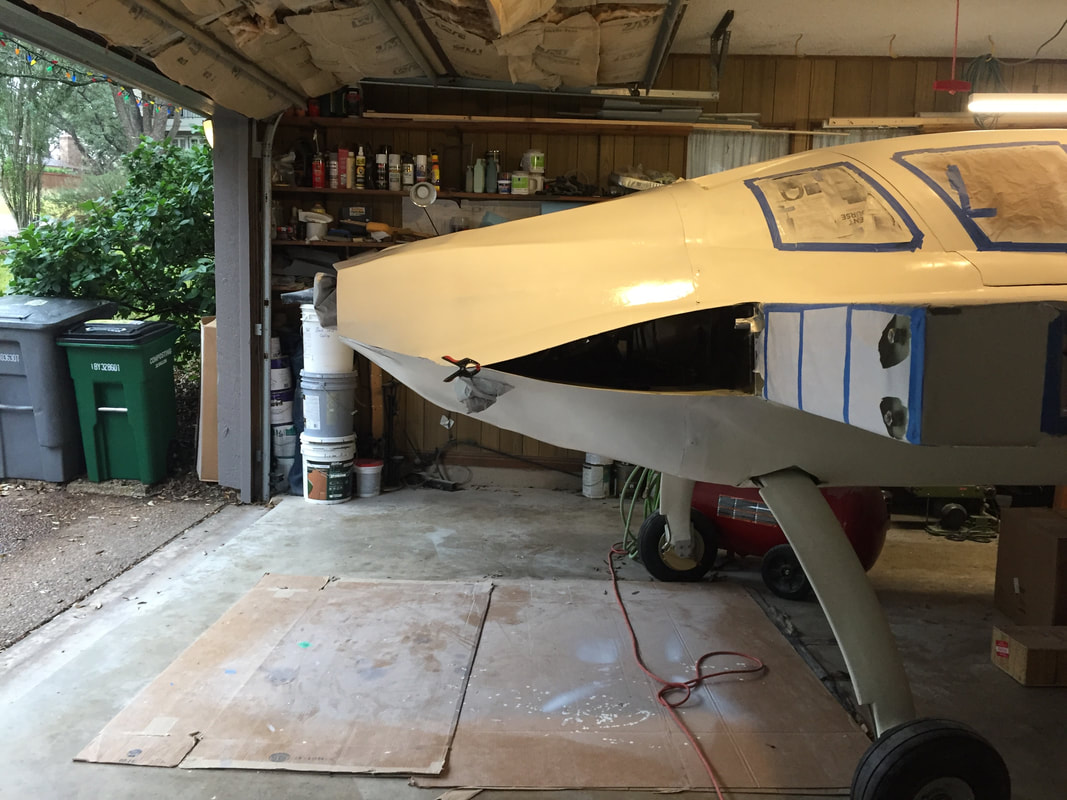
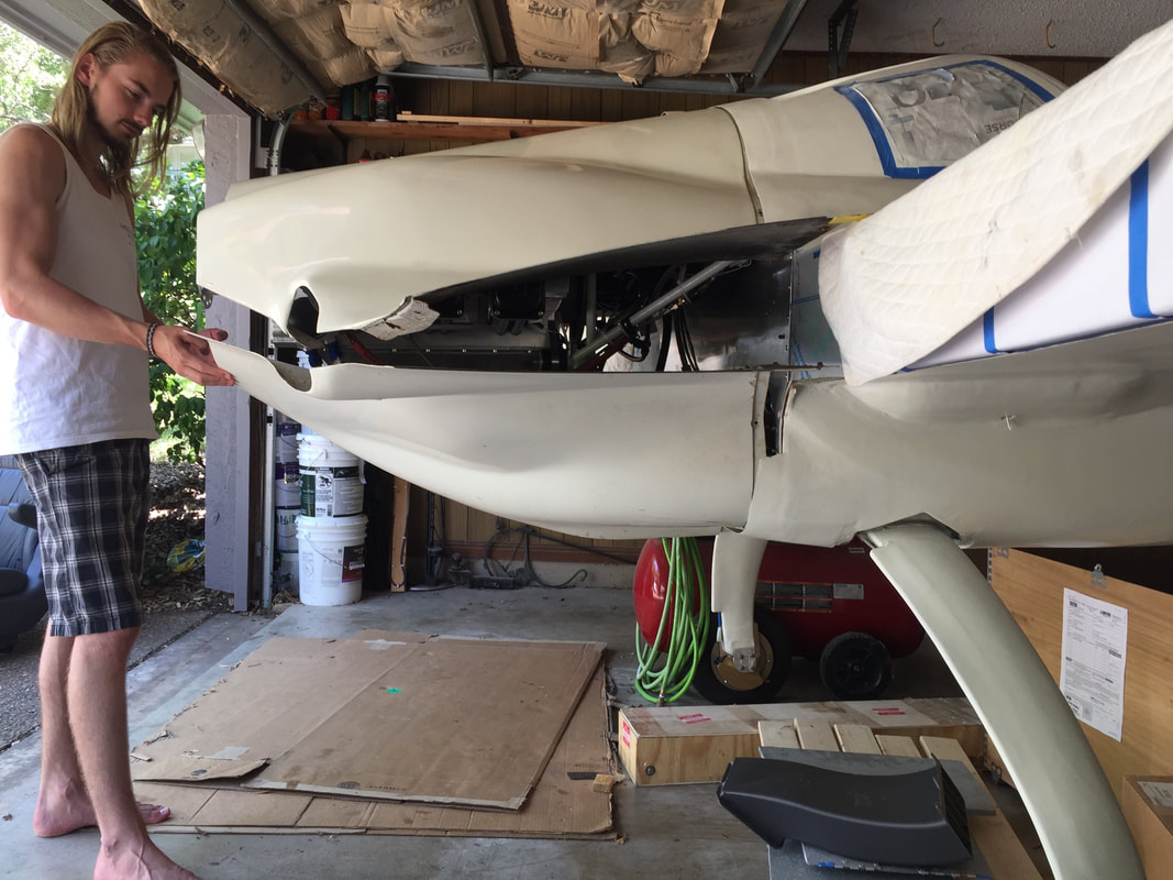
Ch 23.3 Engine / Cowling
I got some great feedback from the Cozy Builders/Canard Fliers lists on making custom cowlings before starting on this. There have been some amazingly innovative approaches to the challenge of building a custom cowling. I chose to build custom for the following reasons:
1. Want the cowling to match the UL engine, which is a little smaller, and mounted slightly more aft than the Lycoming 360.
2. Want as clean an inflow to the UL prop as possible.
3. Want to run my exhaust directly out the bottom of the cowling as demonstrated by Nate Mullins. This is facilitated when the cowling is shaped for this approach.
1. Want the cowling to match the UL engine, which is a little smaller, and mounted slightly more aft than the Lycoming 360.
2. Want as clean an inflow to the UL prop as possible.
3. Want to run my exhaust directly out the bottom of the cowling as demonstrated by Nate Mullins. This is facilitated when the cowling is shaped for this approach.
Lower Cowling
Creating Custom Shape Inside Standard Featherlight Lower Cowling:
I started with the lower cowling since I need to figure out it's shape to determine where to trim/adjust the exhaust pipes to exit the cowling adequately. This little chain of dependency resulted in shift of focus as I was intent previously on getting everything done to get to first start of the engine, and shaking out any electrical, fuel, oil, etc issues prior to moving to hangar. That's just the way it is when you take on something new. You have to adapt to the need, and at the moment, I don't want to start the engine until I've got the exhaust system reasonably well set.
I did not want to turn the plane over at this point to build the cowling in place, and I could not figure out a way to build it without having gravity assist. I decided to build my cowling inside a standard featherlight cowling and use foam to fill the gaps between the standard cowling and what I wanted for the UL engine. Note: this is no small undertaking. I'll go through what I did, but it's not a quick process. Essentially, I'm building a one-time use mold inside the featherlight. Nelson Amen was gracious enough to let me borrow his featherlight cowlings for this process, as he's still a ways from using them. Here are the steps I went through, and a few pictures from the process:
Photos: Ugly up front building the form inside the Featherlight Cowling:
I started with the lower cowling since I need to figure out it's shape to determine where to trim/adjust the exhaust pipes to exit the cowling adequately. This little chain of dependency resulted in shift of focus as I was intent previously on getting everything done to get to first start of the engine, and shaking out any electrical, fuel, oil, etc issues prior to moving to hangar. That's just the way it is when you take on something new. You have to adapt to the need, and at the moment, I don't want to start the engine until I've got the exhaust system reasonably well set.
I did not want to turn the plane over at this point to build the cowling in place, and I could not figure out a way to build it without having gravity assist. I decided to build my cowling inside a standard featherlight cowling and use foam to fill the gaps between the standard cowling and what I wanted for the UL engine. Note: this is no small undertaking. I'll go through what I did, but it's not a quick process. Essentially, I'm building a one-time use mold inside the featherlight. Nelson Amen was gracious enough to let me borrow his featherlight cowlings for this process, as he's still a ways from using them. Here are the steps I went through, and a few pictures from the process:
- Obtain the standard cowling. I'll call this the "SC" for brevity in the following bullet list. Nelson's was a featherlight with a moderate boat tail shape to it.
- Position the SC in place on my fuselage and examine where I wanted to reduce the huge clearances I had. Note that I had mounted the oil cooler in the final position, and had removed the exhaust pipes. I did this by eye. It's not perfect, but there are adjustment opportunities later.
- Mark inside the cowling (removable ink) where I want to do which shaping. The emphasis for my lower were the following:
- Match the skin tangent at the fuselage. The match was good on the sides, but poor on the bottom, in part because I could not lift the trailing edge of the standard cowling as far as normally done with the Lycoming, because I have the oil cooler mounted low and forward of the engine. The pictures help show this point. It was not a big tilt difference, but did require some compensation.
- Pull in the lower rounded corners to create a better flow into the exhaust region, and reduce the overall volume of the lower cowling, while still tapering well to the prop.
- Bring the prop hub area up slightly, to account for the slight tilt of the standard cowling.
- Fill in the area in the lower cowling where the Lycoming exhaust normally flows out the rear
- These areas were then filled as shown with blue foam and pour foam and carved to achieve approximately the shape desired. I ran out of pour foam and it was somewhat hard to work with in this application, because I'm pouring into relatively unconstrained cavities. I chose to use drywall compound for fill small voids in foam and do final smoothing. This process involved MANY fill and re-fit to fuselage to check clearances and overall shape. Using standard joint compound is really heavy and the whole thing got really hard to lift into place for fit checks, so I found lighter drywall compound. The latter didn't sand quite as well but was adequate to finish what was becoming a big job...
- Once I had the shape I wanted I was worried about the epoxy absorbing into the joint compound so I brushed a couple of layers of polyurethane on it and waxed it heavily to provide a good release surface (this didn't work that well, keep reading).
- Just before glassing I became more nervous about the release and taped a layer of pallet wrap on the two flat wing sections, and a strip running up the centerline of the mold. This pallet wrap is very slippery, and I didn't use it in the highly curved areas, because I wanted the epoxy to still a little in these areas to hold the right shape.
- I then glassed the new shape as if it were a normal mold (2BID everywhere and an additional 2" BID on the periphery as a reinforcement for installation hardware. (more BID applied later).
- After 2 days of cure (using MGS 335/340 slow hardener) I performed the release. It was trivial in the wing sections with the pallet wrap, but pretty difficult in the highly curved areas, and then easy again in the centerline area where the pallet wrap was again used. The flexibility of my 2 ply layup helped to get the 1" scraper I used into the foam/joint compound to break these areas loose. Remember, it's a single use mold...
- Once released, I put a 3rd BID ply inside my piece with it just resting in the "mold" and let this cure another 2 days.
- Then I pulled my new lower cowling from the SC and used a scraper to clean 98% of the mess and wire brush for about 2%. on both components.
- buy more pour foam: I tried using Great Stuff again from local home improvement store and this stuff is really easy to spray on where you want it, but it's just terrible to try and sand because it's too compliant. With enough pour foam, you can avoid using joint compound, which I would not use again.
- Don't use polyurethane and wax it: The wax was not really effective in preventing the epoxy from sticking to the polyurethane, and the latter was just messy to get off of both my part, and the SC. Go with tried and true: duct tape.
Photos: Ugly up front building the form inside the Featherlight Cowling:
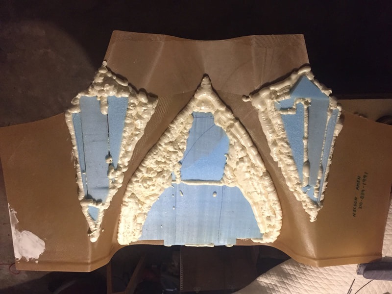
Starting with blue Foam and Great Stuff (don't use the latter where you want to finish sand the shape)
|
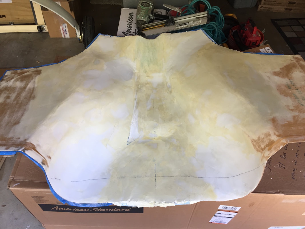
Nearing completion of the shaping of the form inside the Featherlight Cowling
|
Photos: Layup and fitting of the result:
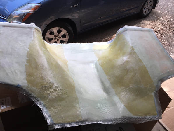
3 ply BID in the form...
|
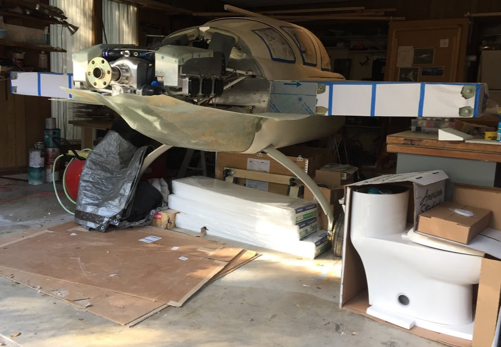
My wife said she would fly with me if the Cozy had a potty, so I'm getting it ready for installation...
|
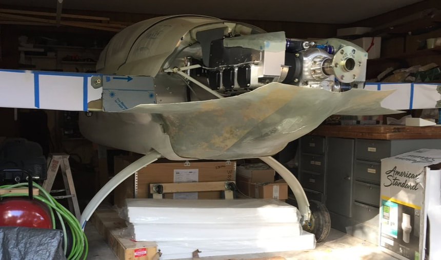
A view of the lower cowling in the initial fit-up
|
Modifications for oil cooler:
The oil cooler was mounted just in front of the engine oil pan and draws cool air from the belly NACA. You can see in photos that I don't think I need all of the sectional area of the NACA for just this cooler (it's an 17 row unit, which should be more than enough according to Nate Mullins and UL). I designed a smoothly transitioning duct and 3D printed it in High Temperature PLA. It's far from the heat of the engine, but is not fire resistant. I may choose later to add some thermal insulation around it. Obviously, the NACA had to be modified for this smaller shape and I chose not to re-design the whole thing, but rather put inserted fillers to limit lateral expansion in the last bit of the duct as shown in the picture. While not the theoretical lowest drag shape, I'm guessing the penalty is quite small. 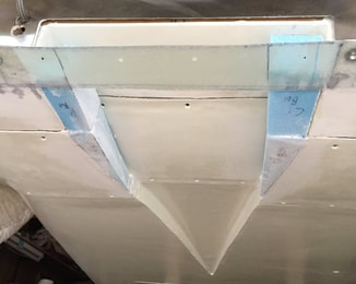
A look at the re-shaped belly NACA for the smaller area needed for my oil cooler inlet duct (early stages of getting this foam filled and glassed...)
|
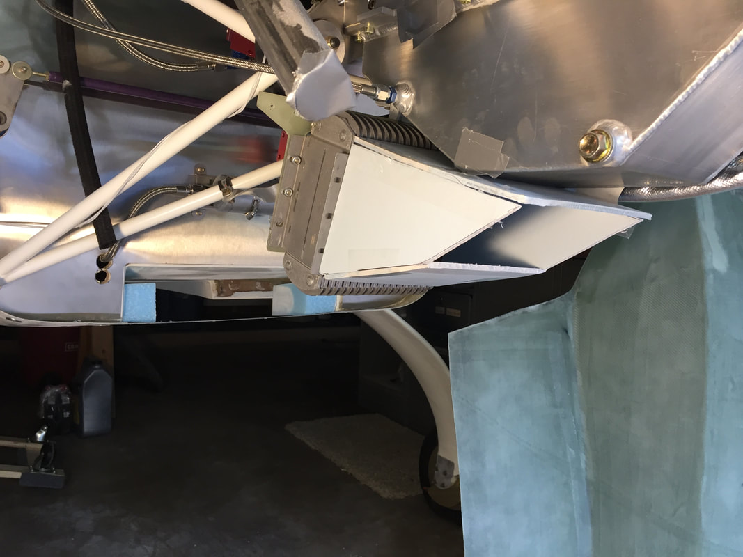
foam posterboard mockup of the oil cooler exhaust duct taped in place. Once I had this the shape I wanted, I unfolded the posterboard out flat and used it as a pattern to cut a single piece of 18 gage 6061 Aluminum sheet. Then bent the sheet back along the lines of this pattern and 1/8" pop riveted it together with integrated flange interfaces to the oil cooler
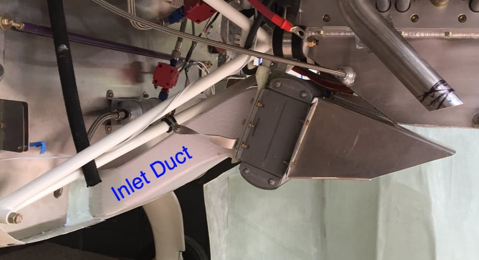
Here's the 3D Printed oil cooler inlet duct. It's made with High Temp PLA and post cured. Contact me if interested in details. Note that I matched the duct inlet area of the oil cooler area + 5% and this was still smaller than the plans NACA, so I've modified the width of the belly NACA and you can see here where I sealed the interface at the firewall with 2BID.
|
Upper Cowling
The upper cowling shape was a completely new design because I wanted to keep the aft aperture small, fit the UL engine (which is mounted further aft than the Lycoming since it's lighter to meet the CG needs), and match the firewall/strake/wing root. I consulted Ryley Karl and Nate Mullins on how to set up foam in the engine area and ultimately used the method below, which borrowed most heavily from what I saw Nate doing with 1/2" pink foam from local home improvement store. In this case I'll annotate the figures more for description. I also show a visual comparison of the featherlight cowls to my custom cowls.
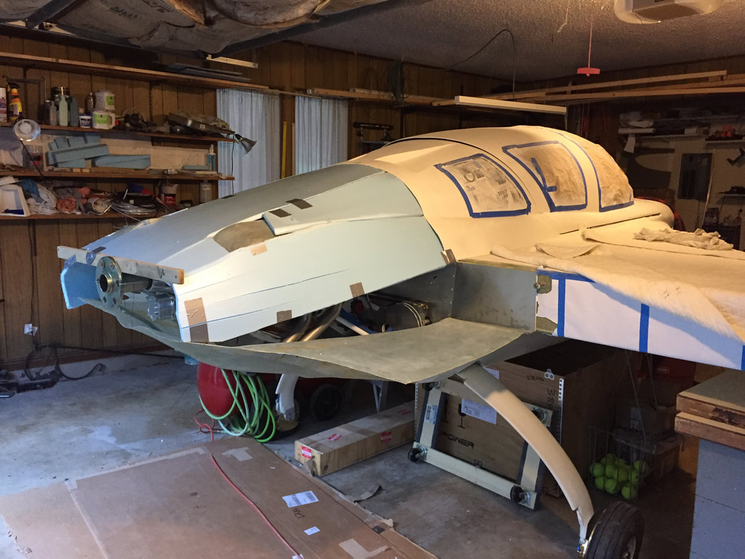
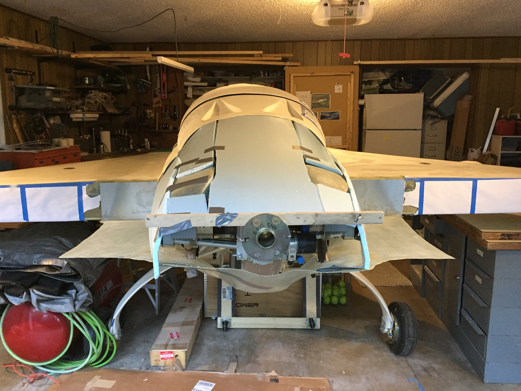
Use of 1/2" pink (Lowes had this in light blue) foam to start getting the shape. Note pieces: top, shoulder (front/back), and side. slits used to allow the foam to bend some. Duct tape pulling toward engine to bend the foam.
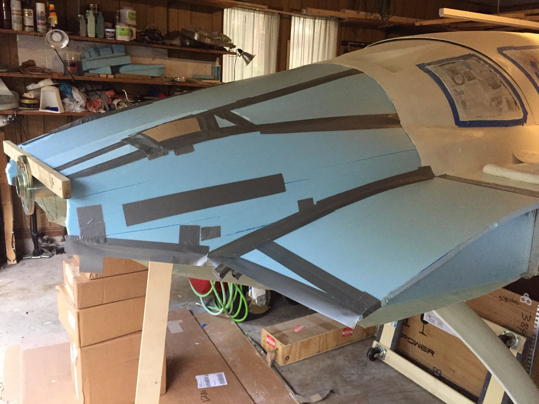
Refinement of the shaping: used some wedges inside to push the foam against the cowling support lips coming off of fuselage. Duct tape on the seams and over larger slits. Took a template off of my wing root (could have used plans, but more convenient to use the real thing) to make frames for the wing root extensions. I used cardboard over the cylinder cooling plenums as I wanted to keep this clearance about 3/8" vs 1/2" of the foam. The level wood piece mounted to the forward edge of the prop flange serves as a friction point on the trailing edge of the foam to allow me to "tuck" the foam profile down a slightly in this area.

After 3 plies BID and cure, I went in with pour foam and filled and sanded the larger low spots. Then micro'd them, and put on another 2 BID over the whole thing.
|
Another view of early foam shape. Down draft ducts helped bend the foam to close to the firewall curvature. Duct tape between top and shoulder pieces are pulling the shoulder down towards engine to create twist. Pretty cool.
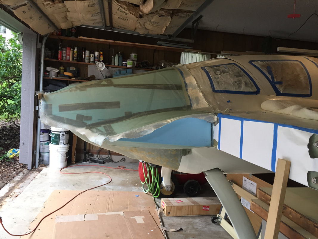
Everything got covered in clear packing tape as a release agent. It worked great in this case because the curves are very gentle and not overly compound, as in the lower cowling (should have used this on the "wing sections" of the lower cowling though). Here's what it looked like after 3 plies of BID
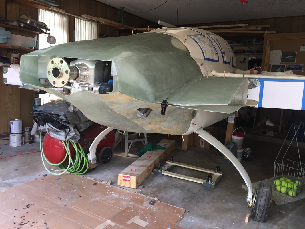
All foam removed and both cowlings attached with cleco's.
The exhaust tubes are visible here poking through the lower cowling.
|
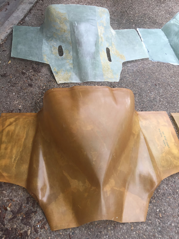
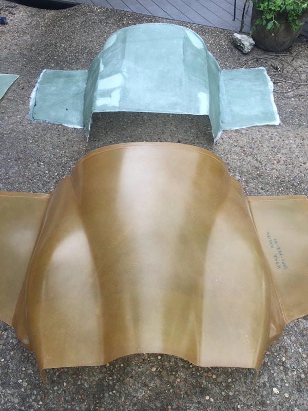
With BOTH cowlings mostly completed and interfaced with TORX screws to the firewall and strake lips, and each other in the back area, additional reinforcement was applied in the attachment edges and beefed up with 3 more BID.
|
Modifications for exhaust:
This was largely a trial and error process and started after I had the lower cowling completed and set up with good fit to the firewall and spar lips, and the upper cowling. At this point, I removed the lower cowling and installed the exhaust tubes as described here. Once holes had been marked and cut I worked on getting the lower cowling on (threading exhaust tubes through these holes). This wasn't easy at first and required some marking and trimming on both the cowling holes and the exhaust tubes. Eventually I got things so that everything looked OK and accepted it for now. I plan to further modify exhaust #3 after running the engine some, so that it does not exit tangential to the cowling, to prevent overheating the glass downstream. Running engine in the interim will be without the lower cowling installed for safety. I'll also be watching the clearance of pipes #1 and #2 with the inside of the lower cowling. The oil cooler exhaust duct was built (see here) and installed and the lower cowling trimmed to allow this exhaust to escape. I still need to reinforce the edges of this opening as well as the exhaust tube holes. It's not pretty since the oil cooler is not centered in the cowling perfectly, and the cowling itself was hand shaped long before the cooler exhaust was built. This will be plenty good enough for the first year of flying, and at some point I may build a new lower cowl and oil cooler exhaust with a better external look. |
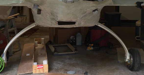
View of lower cowling with exhaust poking out. Central hole is where the oil cooler air exhausts.
|
|
Finishing:
My intent with with finishing at this stage was to get the cowlings pretty smooth and at least reasonably well interfaced with the firewall lip to which they attach. They are custom, so they are not perfect. There were slight mismatches at the corners where the strake meets the firewall, and a little shaping needed in the lower corners and the pinch points between the upper fairings and the upper rounded firewall curve on both sides, but the gaps were at worst 0.2 to 0.25 inches and I used some blue foam in 4 small areas to reduce the thickness of micro required. I went through 3 phases of fill/sand, similar to what I'd done on the rest of the aircraft, and because these are very curvy custom shapes, I could easily have done a couple more cycles. However, I decided that they were close enough at this point that I could get a coat of primer on them and do the rest either with them removed from the fuselage, or wait until after Phase I testing, when I plan to re-sand and primer again and possibly paint for the final smoothness. Below are a few pictures from this phase and I'm happy with the results. Yes there are some pin-holes, and yes there are a some low spots, but they are not noticeable at 10 ft and they should not influence flight performance in any signifiant way compared to not having wheel pants for instance... 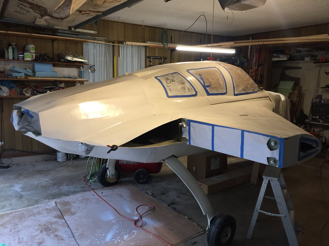
Cowlings after 1st coat of primer and tent removed. They look pretty good for as quick as I got all this finish work done. I'm very happy with the shape with this engine and exhaust and oil cooler configuration.
Notes: painting the underside was difficult with gravity fed HVLP spray gun. The gun can leak from top of paint holder if it's not screwed on tight (as me how I know...), but it worked out fine. The lower cowling micro/sanding/painting included doing same to the lower NACA modifications and inlet to the oil cooler. Not easy working under the belly, but doable.
|
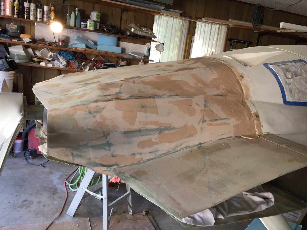
2nd pass of micro fill on the upper cowling. Emphasis here is on getting good match with the firewall tabs.
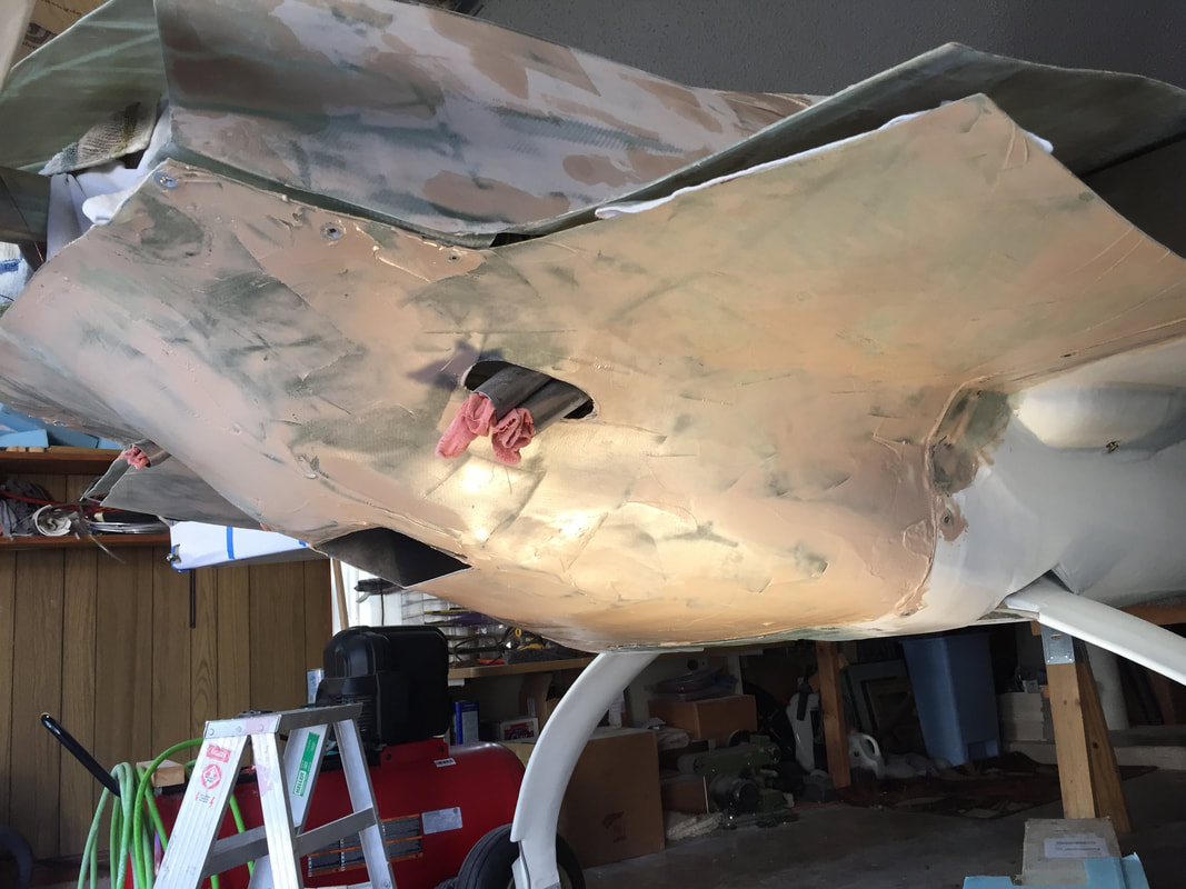
2nd pass micro for lower cowling. Same emphasis as upper cowling for this pass
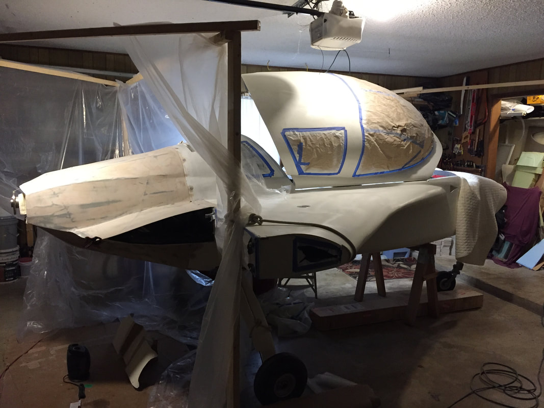
I built a tent in the garage that prevented spray from going forward of the NACA's (top and bottom) so I could shoot the primer with the cowling mounted. The reason for this was to get good primer on the cowling/firwall lip interface without having to mask the whole engine. There was still masking of all cowling and engine compartment access holes. Later micro and smoothing will be done with cowlings mounted, but painting will be with them removed for good shooting angles.
|