Chapter 24: Seats, Arm Rests
I jumped back to Ch 24 once I had the Controls done for Ch 16 because I wanted to make the arm rests while I had the fuselage on it's side. Later when I complete the canopy/turtleback and get the spar mounted I'll be forced to work INSIDE the fuselage for this, which seemed to me to be less comfortable. You'll see I'm making portions of the armrests removable so I still have access for later work but will have all the components fitted, so when I get to the end, I can just assemble them into the fuselage and move to finishing... At least that's the plan.
|
Forward Arm Rests:
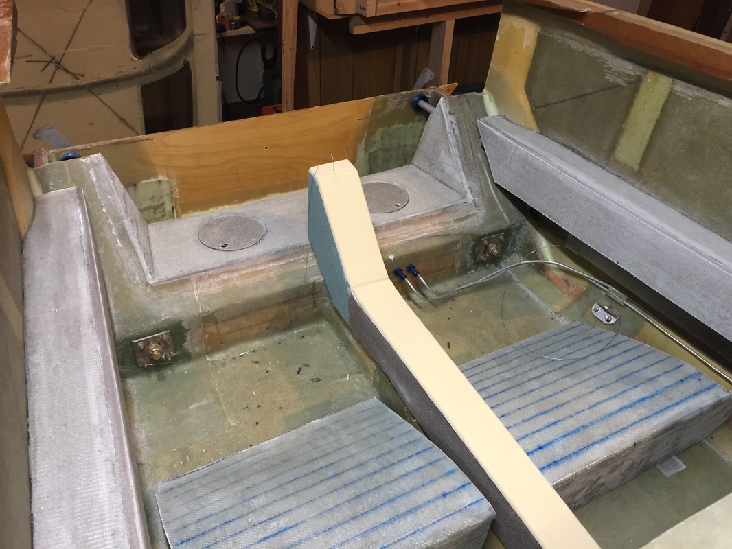
Once I had each side's Control torque tubes mounted (Ch 16) and I had the fuselage on it's side for ease, I jumped forward and did the arm rests, starting with the Forward then the back for each side. My design for the arm rest was derived from the observation that the window openings from the turtleback that I'd cut out in Ch 18 were super strong and stiff and thin and light. Part of this is provided by their curvature, and the fact that they had 2 UNI on each side, but I figured I could use this 0.2 foam (which I had extra of) to make the downward sloping portion as shown in the finished figure of the arm rest. I stayed with the plans 3/8" PVC foam everywhere else, but modified the plans design slightly to use fewer pieces and capitalize on what I saw others doing online. a) I wanted to avoid the large size opening for the joystick and saw that others like the CozyGirrrls had not left the side open (more on this later). b) I wanted to keep the hip/torso region as wide as possible. I'm not a big person, but for long flights every inch of elbow room can help. c) I knew I didn't want to glass all the armrest in, because I have all the electrical wiring still to do (already built and installed electrical conduits - see Ch 16), but I also wanted to have most of the armrest glassed in place now, so I only had to do a little fitting later when the turtleback was on. All the panels are single BID on both sides. The first picture is with the removable lower front section removed. The sequence I used for this permanent part is as follows: (I have more pictures on this if someone has specific questions in this area) - mold the map pockets (I used a thin box as the template for both map pockets in one molding and then cut them apart. - shape the arm rest top foam to the fuselage curve, the joystick bearing mount, map pocket, and seat back. - mark the fuselage for armrest top and map pocket locations and epoxy the map pocket to the fuselage (mine had 1/2" flanges to allow good bond area). - Fit the downward sloping side to the seat back and top foam then glass both sides of these panels, trim, and install. I used 5 min epoxy to attach the white side panel to the under side of the armrest top and later I'll tape the curved surface. Top panel floxed and taped in place. The second picture shows the removable forward portion of the front arm rests from inside and outside. Note that I had to Dremel the inside some to maximize joystick movement, and once the wings and ailerons are all mounted I may have to open a small slot and put a blister on the outside if I need more angle from the joystick. We'll see. These two panels are floxed together and fitted in place as shown in the last photo of everything together. The removable portion is secured with 6 SS 6-32 bolts coming through the Instrument Panel from the front (there are threaded flox blocks built into the foam of the removable panel). I did make a support post out of 3/8" foam/1BID sandwich to support the lower/forward corner of the white armrest panel so its not vulnerable to my shoes later when I'm turning around/working in the cockpit. |
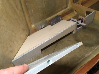
Glassed in portions of forward arm rest (top and rear slanted panel). Also shown are the foam openings prior to building the flox blocks that would be drilled and tapped for the removable side panel (see text). The weight shown is for cure of bonding the support post under the white panel (see text).
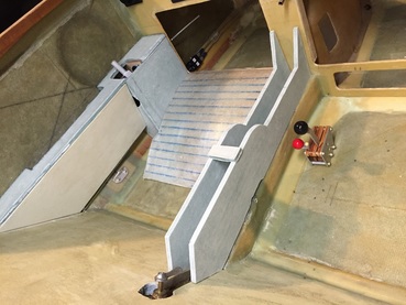
Here's a look at Pilot Arm Rest with the removable forward section installed. (Sorry, awkward camera angle...) Center console is covered more below (when I get time to finish and document it).
|
|
Rear Arm Rests:
The rear arm rests were built according to plans and just fitted. This is not hard but it takes patience to get the fit well. A couple of things to note: - the control tube was a little more inboard at the aft end of the arm rest than I was expecting, which required a slight twist in the side panel to allow clearance for the bolt that connects to CS-122. I used weights and a support post (just like I did for the lower corner of the white panel in the forward arm rest) to get this proper twist, and once everything was floxed, the system is very solid. If I were doing this again, I would have cut the upper arm rest panel 3.5" wide instead of the 3" of the bearing support, which would have allowed for shaping the outboard edge to the fuselage, while allowing a slight curvature on the inside edge to maintain this clearance at the back. This may also have been caused by my working with a fuselage that was 2" wider than plans, so the angle of torque tube is slightly larger... At any rate, it's not a big deal. The arm rest looks good, and I think may be slightly more comfortable with <5 degree angle I put in the top panel back where your elbow would be. - I bonded in the top and side panels and though I built the sloping lower side panel, I stored it for now so I can retain access to the conduit area. 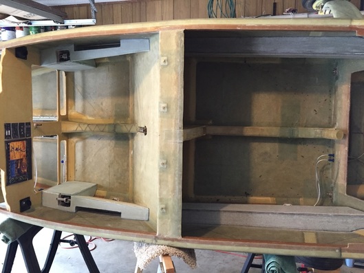
Finished arm rests on both sides. Way easier to fit and build this one side at a time using gravity to help. Dreaming of instrument panel...
|
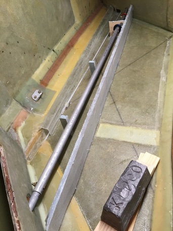
Top panel of rear arm rest AND the two support posts (spaced aft of the bearing support block) that will be the bonding surfaces for the permanent side panel.
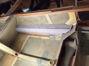
Rear Arm Rest (photo rotated upright). The lowest angled panel is removable.
|
|
Seats: I've built up the thigh supports following the plans method and geometry (making a template from M12, M13 front and M15 rear). I ended up making the rear supports 1/2" shorter than plans since I believe I'll not have full sized people back there for very long and it better matched the foam material I had on hand. The shaping method is pretty cool (glass one side of the foam, cut the foam in strips to allow it to curve, then micro and glass the other side with it bent over the thigh support ribs). I decided to make the ribs and thigh panel one unit and rather than hinge it at the back, just secure it with bolts (2 through the instrument panel and one in the back into the floor. The reason I can do this is that I don't have the roll trim running under these thigh supports (see Ch 17 Trim). Anyway, I don't think I'm going to take them out often, and when I do, I'd like them all the way out and the floor clear. There are other pictures below that show the finished seat thigh supports front and back. |
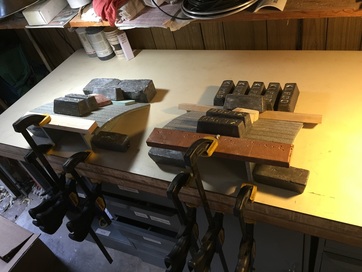
Flexing the thigh support over the Ribs (flox along rib line underneath) to set the curvature of seat prior to micro/glass of top surface. These happen to be the rear thigh supports. Yea, I get a little crazy with the weights and clamps sometimes to get a good tight bond.
|
|
Landing Brake Actuator Cover:
I'm part way through this. I've built the cover but not yet equipped it and the seat back for the removal screws. I've included one picture of how I designed mine with a little bit of angle to the top piece that's different from others... I'm not assuming mine's any better, I just thought I'd be a little creative with it. |
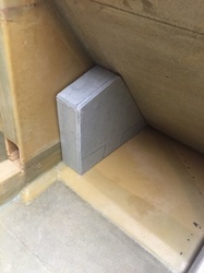
Landing Brake Actuator Box (initial assembly)
|
|
Center Console and Quadrant:
I'm part way through building this and have included a photo of the design. The quadrant and top will be removable. I'll get an updated photo in here when I finish curving the top piece and it's done... I'm just fitting this in when I'm not working on something else more significant... |
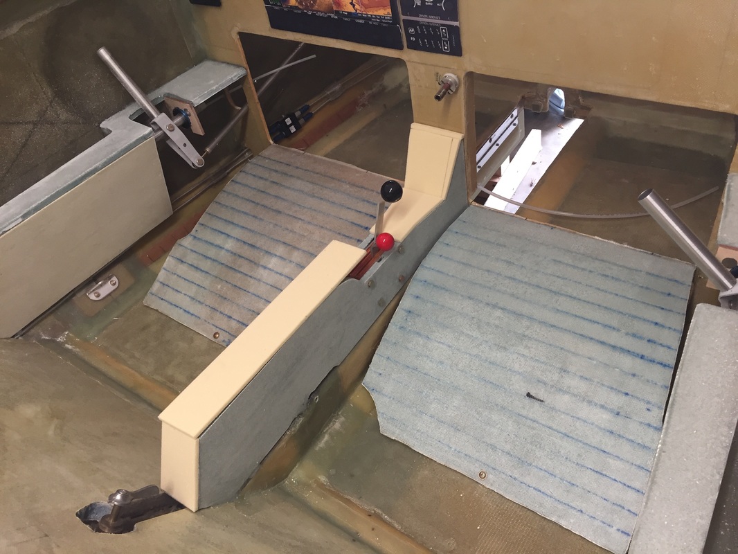
initial foam fitting for center console
|
Aft Heat Duct Cover/Center Console:
I have built the foam up for this but not glassed the outside (inside is 1 UNI aligned on the long axis). Outside will be 2 BID per plans. See next section last photo for view of it.
I have built the foam up for this but not glassed the outside (inside is 1 UNI aligned on the long axis). Outside will be 2 BID per plans. See next section last photo for view of it.
|
Main Landing Gear Box Covers:
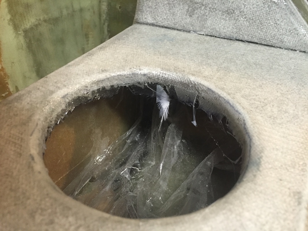
There's no discussion of this in the Plans so I'm following what most builders have done over time, which is basically to provide some form of cover to improve the clean look in the back while retaining access to the main landing gear bow for inspection purposes and simpler routing of throttle, etc through this cavity. The cover's are not structural so they are made with 3/8" foam I have around from armrests etc and 1BID inside and out. The I've taken a couple of pictures to show how I got the glass to lay in the holes (which are round down from the top side). As I write this entry, the layup is still curing. I'll have to update with final photo to confirm all this worked well...
The "holes" I used to press the glass during cure don't look bad, so I think I'll just leave them in, and pop them out with screw driver when I need access (see below).
|
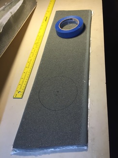
I started by measuring and fitting the foam to the bottom and two sides of the main gear box. I then sanded the front and back edges of the main cover to allow the top glass layer to lay nicely with the front and back box walls. This picture is where I used my masking tape roll as the template for each whole (yea, that's in the plans... not!) AFTER I had glassed the lower side. I then drilled a 1/2" hole near the inside edge of each hole and used my Blade Runner saw (poor man's band saw) to cut each hole, glass side down. Save the holes...
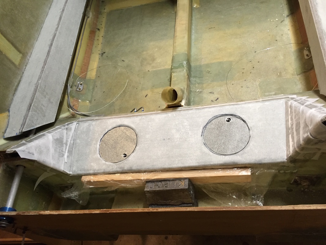
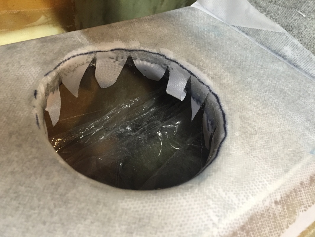
All glassed down and peel plied. I'm using the hole cutouts to press the glass against the inside of the holes during cure. You will need to cut the glass circles about 1" diameter smaller than the real hole (I found another tape roll in my shop that was a good template for marking the glass and using a roller cutter...) You will also need to make at least 12 radial cuts in both the glass and the peel ply to allow it to stretch and push against the side of the hole.
|
Will continue here... last updated 3/17/16
|
Resuming work on Rear Center Console and Back Seat Backs
It's Feb 2017 and I'm getting close on finishing the strakes and center sump which is also the right rear thigh support. I built a larger right rear thigh support for this center sump and constructed it following the process used for the strake tanks, so I have an "extra" unused rear thigh support... All this is documented in Strakes II page. I've also decided at this point that I'd like to paint the interior before cluttering it up further with the wiring I'm going to do when I finish the Strakes, SO: - I spent time final fitting the after center console and glassing it's outer skin. I made this outer skin overlap down onto the heat duct and it will be attached with 4 x 8-32 screws (so it's removable). I have lots to do still under this center console with throttle cable etc. - I spent time re-fitting the arm rest lower panels and the landing brake actuator cover and making them also removable with 8-32 screws - I didn't like that deep corner in the forward floor to front seat back (thought it looked like a place for dirt and stuff to collect and hard to clean) so I made a small toe piece about 1" height from left over strake skin material and floxed/microed it in on both sides. - I generally cleaned up BID tape seams with micro and lots of sanding to get ready for this painting which is covered in the finishing/Interior page for Ch 25. - I also realized how much I used the front thigh supports as places to step and decided to reinforce the center regions of these with 2 more BID layers. - And I finally re-addressed my dislike for the rear seat backs as described below and some figures to the right. Rear Seat Backs. I think the rear seat backs from the plans are too small. I may not be carrying upholstery in the back all the time so I wanted the seat backs to also provide somewhat of a closure to the rear cockpit in that condition. So I took the original seat backs and mounted them in the floor with hinges as recommended and then took left over strake skin material (already glassed on one side) and made extensions to fill out the space between the center console and above the arm rests. Note that I also had my seat backs run up the the upper part of the spar rather than the lower part of the spar. This hides the spar openings, and I'm not planning to make close outs for them. It also makes the rear seats slightly more upright, which I think will be more comfortable for all but very large passengers, which don't fit well back there anyway. Since these backs are longer than plans, I also glassed on a stiffener of at least 2 inch wide 3/8" PVC with at least 2 BID layers on the aft face of each seat back when glassing on the lateral and vertical extensions, and another couple of BID on the front face of the seat backs. 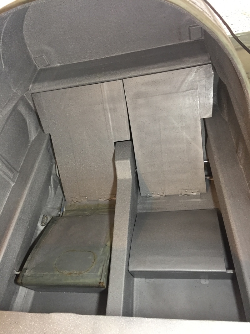
Here's what the bigger seat backs look like much later, along with the center console cover, and the right thigh support grown to become a center fuel sump. And everything painted... about a year after making the initial seat backs and thigh supports.
|
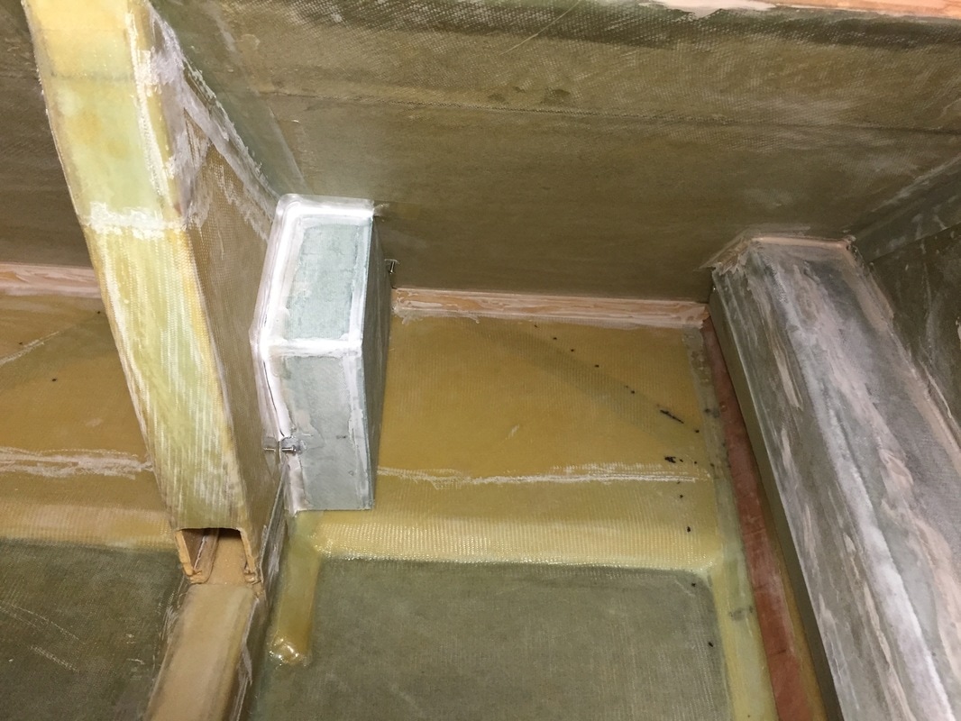
seam finishing on landing brake cover AND you can see the toe pieces I put in at the bottom of the front seat back to conceal that deep sharp corner. Lots of filling and sanding in preparation for painting the interior too.
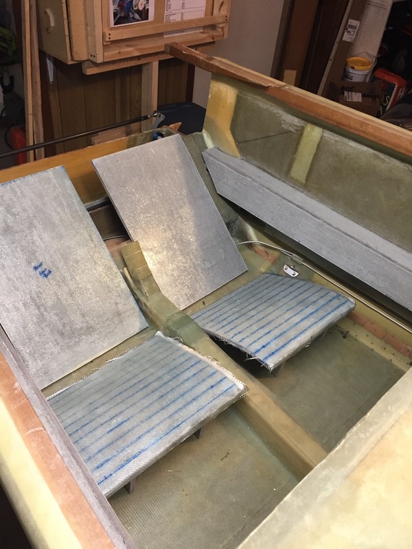
This is a look at the 1st set of rear seat thigh supports and seat backs that I built per plans
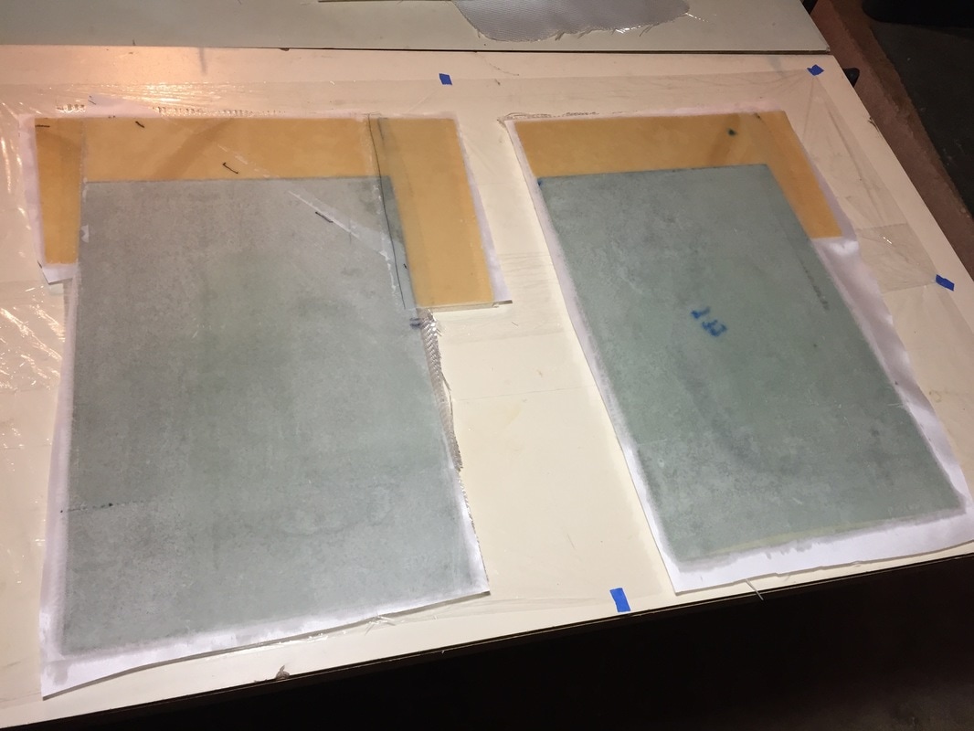
Here are the larger seat backs under construction
|