Chapter 21.2: Strakes (Bottom Skin through Preparation for Top Skin final bonding) |
|
This page picks up where Ch 21 Part I leaves off: The top skin T-hats are done, and the top skins have been stowed for later final bonding to T-hats. Now I need to build the bottom skins and complete the strakes to the point that they are ready for fuel tank seal test.
|
Turning the Fuselage Over:
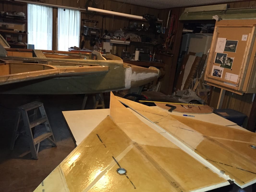
I've read a lot about how to do the bottom skins and have decided that since I learned how to do the top skins well by working from the top, I'd continue that technique for the bottom skins. The down side is that I need to turn the fuselage over for this. Bernie Siu turned his Cozy over for this and was willing to ship me his "clam shells" which makes turning it over much easier. These bolt to the outboard wing bolt holes in the spar, and are the rolling pivot for pitching the fuselage over it's rear end. I need to get all the canopy and canard and nose top off for this, to keep the weight low and reduce the possibility of damaging something when it's upside down. I also figured I'm going to have to learn to do this since I'll want to flip it over to glass the outside of the bottom skin anyway... To the upper right is a picture of Bernie's clam shells on my spar. Thanks, my friend. More directly to the right is a link to YouTube video of us flipping the Cozy over in the driveway. It's pretty easy with 3 people, and might even be doable with 2. Here's the link to Bernie's web page on the fabrication and use of the clam shells: www.cozy.simpex.com/Ch21_07.html |
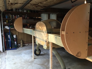
Bernie Siu's "Clam Shells" mounted on my spar in prep for flipping the system over.
|
Make and Fit the Bottom Skin Panels:
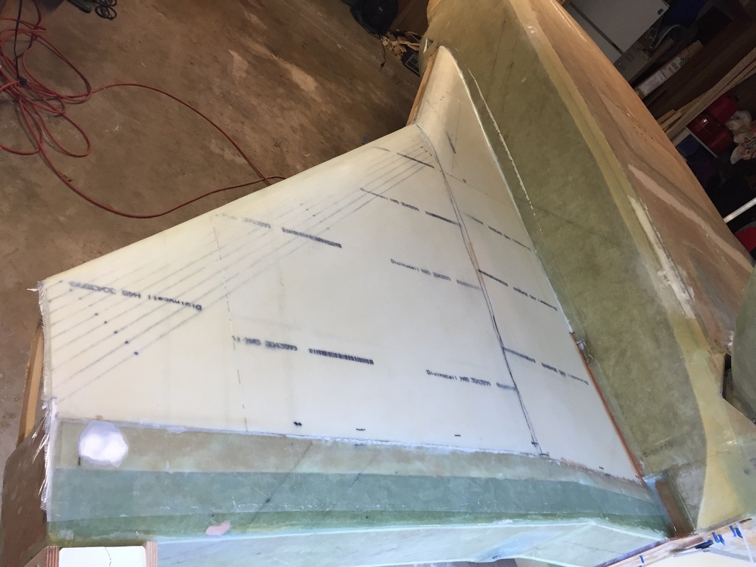
II used the same method to bench build the skin panels and fit them to the strake frames/ribs that is described in Strakes Part 1 web page for the top skins. In fact, I used the same paper templates, knowing that the bottom skins will be a little smaller. The extra would get trimmed away during the fitting process. that I used for the top skins, and will fit them using the same process. Since I'd flipped the fuselage over, working with the bottom skin was almost the same as the previous fitting process for the top.
II used the same method to bench build the skin panels and fit them to the strake frames/ribs that is described in Strakes Part 1 web page for the top skins. In fact, I used the same paper templates, knowing that the bottom skins will be a little smaller. The extra would get trimmed away during the fitting process. that I used for the top skins, and will fit them using the same process. Since I'd flipped the fuselage over, working with the bottom skin was almost the same as the previous fitting process for the top.
|
Flox and Tape the Bottom Skins:
Once the bottom skin foam panels were fitted (many "on, mark areas for trimming, trim, and re-check fit...) it was time to get them floxed and taped. This is a lot of taping work in one session, so preparation is key. The whole process took 5 continuous hrs even though I was pretty well prepared for each side. I did them about 5 days apart, mostly to rest and be well prepared since it's no small task to work with the mask on in 85-93 degree temps early in the mornings. Part of the preparation is being ready to lay the tapes accurately and quickly. I made the tapes (Peel Ply and BID) pre measured on the bench on pallet wrap surface (the plastic roll in the photo to the right). Each tape was numbered on the Peel Ply according to a diagram I'd made of all the edges that were being taped. I'll get a cleaned up version of the diagram on this page soon. Another preparation step was to get the baggage access holes cut in the side of the fuselage. This is much easier to do before either of the skins are attached. The corners of these openings were created first with a 1.25" hole saw. The connections between these holes were cut with the multi-tool with the round saw blade. This is just the rough cut for now as shown in the figure to the right (after I'd applied the tapes). Before I wet all the tapes, I built up the flox to bead up on all the frames and ribs just like what was done for the T-hats. In this case however, I only used the BID on the flox bead of R33 since it's purpose would be to assist with bonding the inboard and outboard panels once they were floxed on the frames. Once the panels were fitted, and weighted and clamped, a little more flox was made to insure a smooth fillet on the inside Leading Edge (LE) and any edges that were about to be taped. It didn't take much extra flox other than at the LE, since the squeezed flox formed a good fillet. The other prep before tapes went on was painting epoxy on the contact surfaces where the tapes would be applied (inside of skin and on the frames/ribs. This allows good adhesion with the pre wetted tapes from the bench. All the actual taping was done on my back on the floor of the garage. Unfortunately I have to reach just a little to insure they lay nice. I used a chip brush to smooth down the peel ply without sticking. After cure, a UNI + BID layup was applied across the B33 seam to seal it up under the 1/2 rounds. |
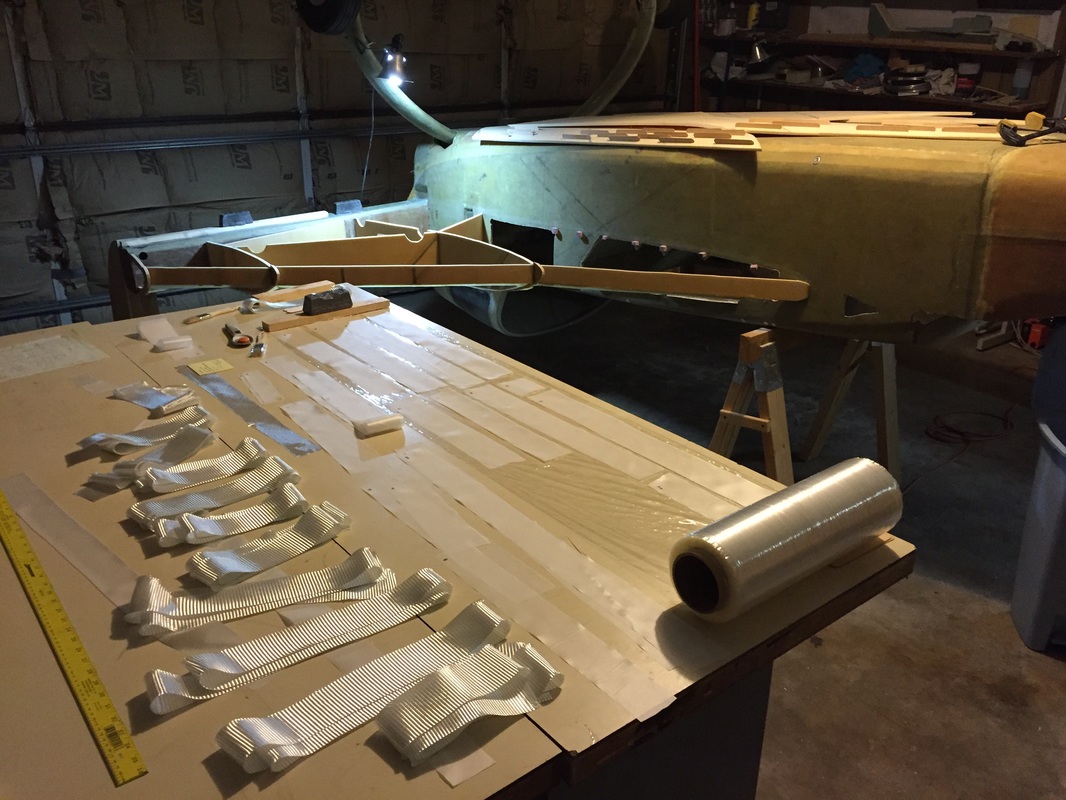
My tape layup preparation area and the strake work area. The panels to be fitted are resting on the fuselage, waiting to be floxed.
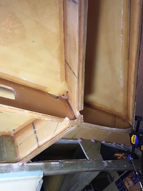
A view of the tapes (looking up from under the upside down fuselage), and the associated rough cut baggage access holes in the fuselage. The pink blocks are temporary supports while the skin is being floxed
|
|
Glassing Outside of Bottom Skins:
At this point I cut off the nose tip profiles from R33 and R57 and my end rib. Other builders have noted how it's hard to wrap the skin profile well over the LE bulkhead with these protrusions and they will be floxed back on when it's time to shape the leading edge foam... With these removed I spent about 3 more hours doing minor sanding on the outside of the bottom skin foam with 60 grit paper and 8" and 24" backing boards to insure no major high spots. I didn't get a flat spot as others have described, between R33 and R57 and perhaps the tongue depressors that I used to hold curvature for the couple of weeks between fabricating the panel and this final shaping helped some. It certainly resulted in some lasting curvature in the panel when they were removed, but I observed this relax some over time, so I wouldn't bet it would work in all temperature conditions. I actually got a little bit of a flat spot right where R57 is, because I may have put too much localized weight in that area when curing the flox/tape procedure described above. This was smoothed in by taking a couple of high spots on either side down slightly. It was great going back to MGS for this outer skin and the 2 plus of UNI oriented per plans. I did use EZPoxy flox in the seam between skin and fuselage where the fuel sump would be, as part of the overall approach to have nothing but EZPoxy based surfaces touching the fuel. The picture to the right shows how clear the resulting 2 plies came out (using MGS 335 again). It's hard to tell that there's glass and Peel Ply on the foam in this picture. I was pretty pleased with the outcome, which included a 1/2" radius fillet along the skin/fuselage contact line and the required 4" of overlap with the spar bottom face. Note that it took 5 hours to complete one side, even though I'd pre-cut and fit the glass. When I did the other side it only took 4 hours. Don't underestimate the time needed to keep everything really smooth in each ply, and finish with a good peel ply (not too wet, not too dry). |
UNI glass on bottom skin with Peel Ply. So clear it's hard to tell it's glassed without looking at the edges.
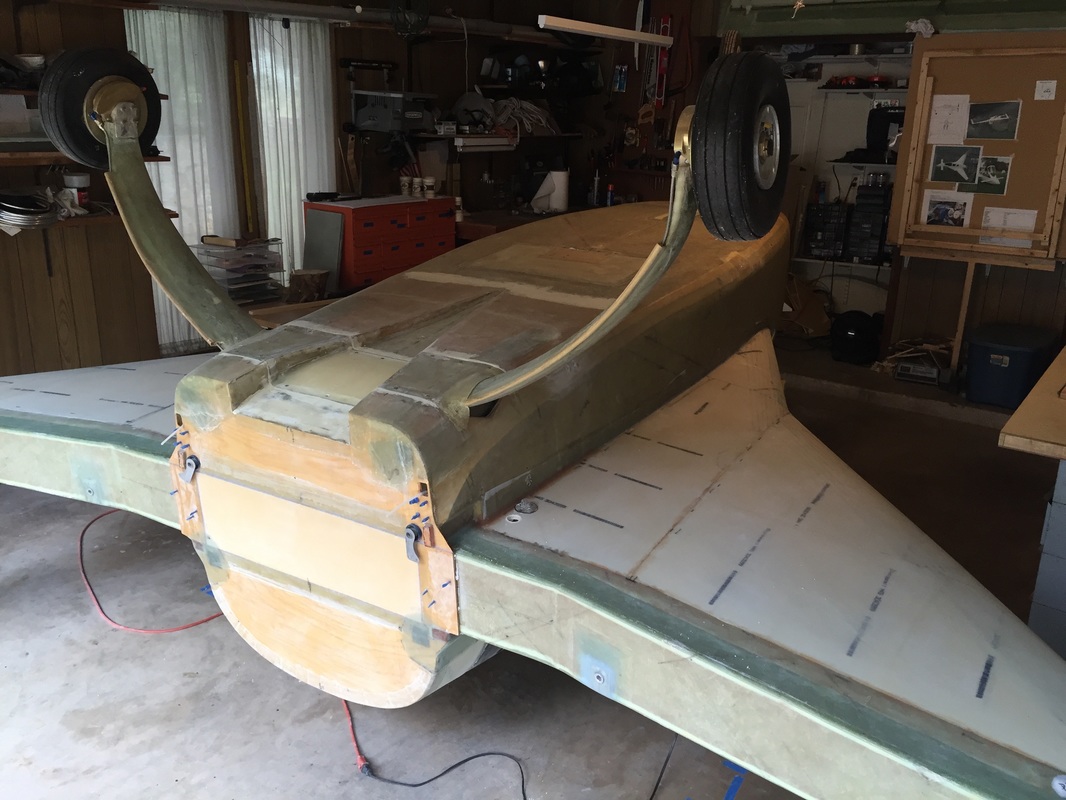
Both sides: Bottom strake skin glassed
|
|
Footnote: I didn't doo this but wish I had...
Russ Meyerriecks posted this after I'd finished my Cozy and I like the idea. In the original Cozy design there are strip copper antennas buried in the wings, winglets, fuselage and canard for Nav and Comms. Russ reached out to Jim Weir about design for a dual frequency antenna for the ELT, which was not required back in Cozy development days. The ELT operates at 121/406MHz and the arm lengths Jim recommended were 22.5" and 6.3". Russ buried his ELT antenna in the lower skin on one side strake as shown in photo to the right. It's not been fully tested for all frequencies yet, but apparently worked well in test at 406. and I like it better than the whip antenna I'm using behind the pilot's seat... |
Russ Meyerriecks' ELT antenna
|
Sumps and Fuel Lines:
While upside down, I'll get the sumps built; but to size them, I will trial run the fuel line and make the tapered hole from the main tank. I'm going to use a center common sump under one of the back thigh rests, and not have a fuel selector up in the front seat area. I will have a remote cutoff valve I can actuate from up front. This is following the method Vance Atkinson has used for years in his Cozy and I've got some design work to do on the sump still. Note that I've talked with Vance several times and looked carefully at his sump system before considering doing this. I'll post description and pictures of what I'm doing once I have it completed. It's a significant deviation from the plans, so I'm not advocating it for anyone else until I've successfully flown it for a while... many moons from now.
While upside down, I'll get the sumps built; but to size them, I will trial run the fuel line and make the tapered hole from the main tank. I'm going to use a center common sump under one of the back thigh rests, and not have a fuel selector up in the front seat area. I will have a remote cutoff valve I can actuate from up front. This is following the method Vance Atkinson has used for years in his Cozy and I've got some design work to do on the sump still. Note that I've talked with Vance several times and looked carefully at his sump system before considering doing this. I'll post description and pictures of what I'm doing once I have it completed. It's a significant deviation from the plans, so I'm not advocating it for anyone else until I've successfully flown it for a while... many moons from now.
|
In the interim, I'll publish some progress and lessons learned:
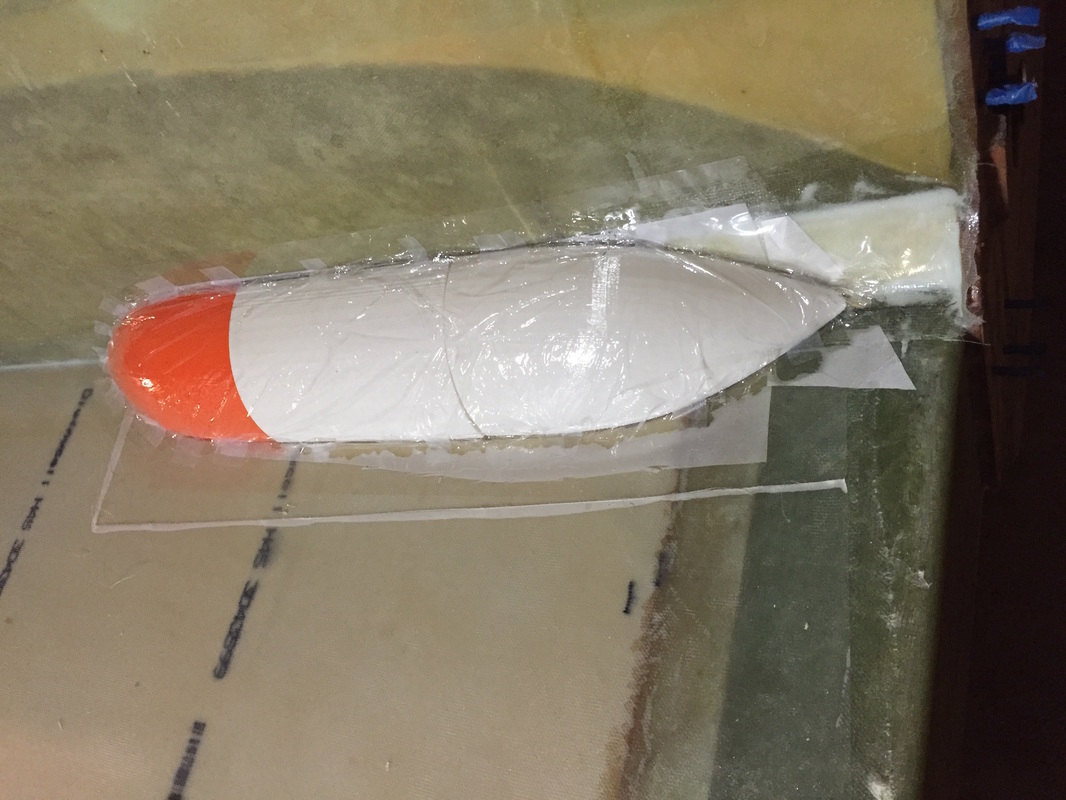
1st Iteration of side sump blisters: I wasn't comfortable carving the blister from foam and attaching it and taping it as called for in the plans, so I designed the blister shape in CAD and 3D printed it in PLA. It's a pretty simple cylindrical shape with a nice smooth spline taper on the front and back. I took the warning of others who used featherlight blisters that they might not fit the angle perfectly between strake and fuselage, so I measured the angle for my Cozy (97 degrees) and used that in the plug design. Then I thought I'd get sophisticated and do a vacuum forming of the 4 BID over this "plug" to give me an inside flange for improved sealing of the fuel. This turned out to be a bad idea because the bend for the inner flange is 90 degrees and despite the vacuum, the 4 pre-wet plies don't like making this bend when they are already bending to the external tapers at the shoulders of the plug*. I didn't like the result with the shoulder wrinkles and though the blister was nice and light, I got smart and went back to the plans method - but using the 3D plug hot glued to the fuselage temporarily for the layup. Some other things I did to help with release on a 3D shape like this was use a thin layer of pallet wrap cut with scissors to fit the outside shape of the blister and taped with scotch tape to the packing tape called for in the plans for the fuselage and strake bottom for release. I still used a layer of Peel Ply against this pallet wrap and a layer on the outside for later finishing/painting. The inside peel ply would enable one more sealing coat of EZPoxy even though I'm building the blister with EZPoxy for good measure fuel resistance. *the problem I saw with the wrinkles can be solved with more careful vacuum layup with a part shaped like this. I use a method of pre-wetting all the ply's on what's going to be the exterior palette wrap seal in a flat orientation on the bench. Once it's wetted out flat, the multiple BID layup will not permit the fiber movement to keep these sharp compound curves smooth. It can work with 1 or 2 BID, but not 4. The plans method is better for these sumps, but if I were attempting something like this again, I'd wet the glass on the plug and bend each ply by hand, then put the outer pallet wrap on and vacuum it down. Lots of work, but I don't want to say it can't be done. 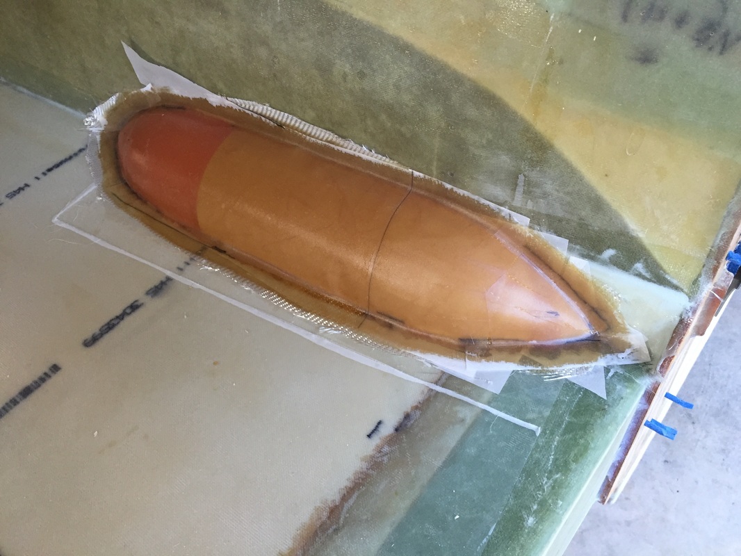
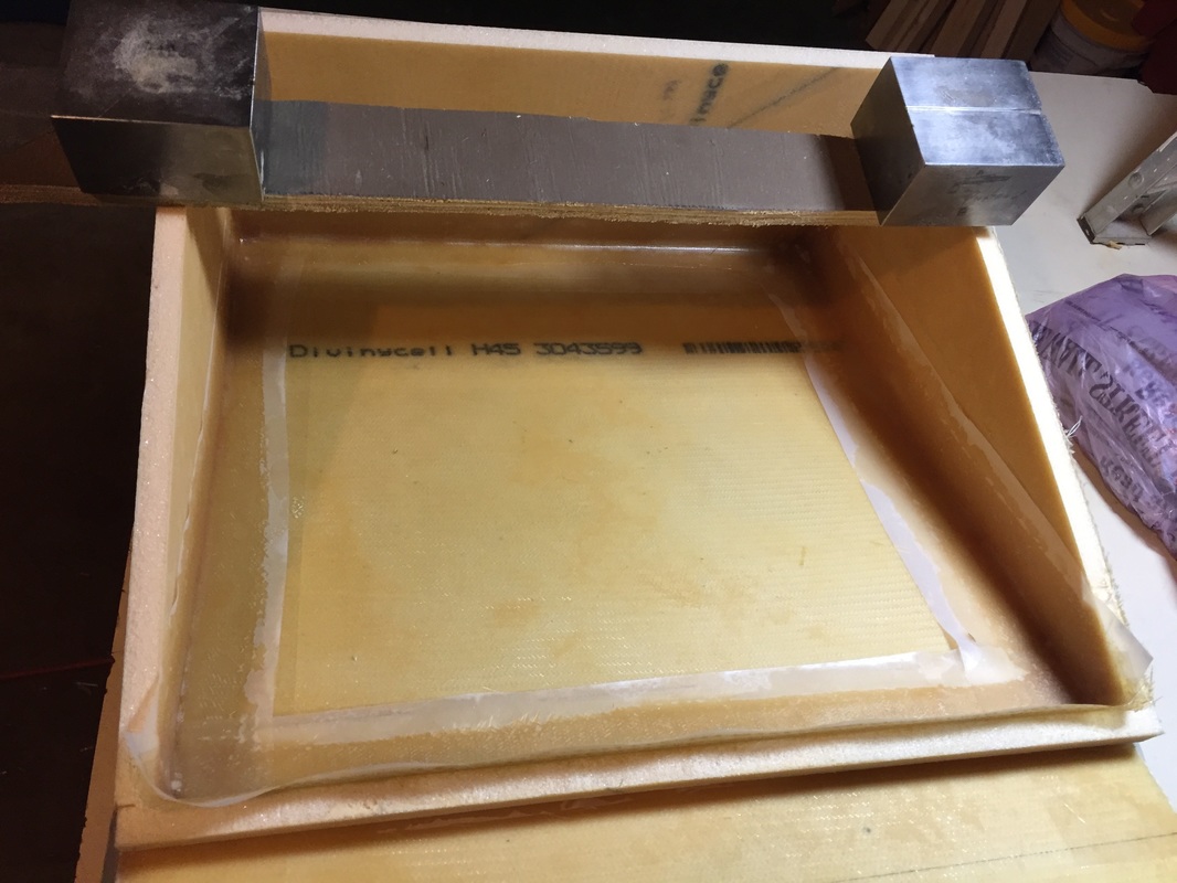
Sump blister 4 BID layup and peel ply with external flanges. Very good fit now...
Completion Step:
After getting the common sump (see below) finished to the point that the fuel feed lines are solid floxed in to it's side walls, I flipped the plane back upside down for a couple of days to flox the flanges and 1 BID tape them to the fuselage/strakes per plans. Then I flipped it back right side up to continue work on both the center sump and strakes in general getting ready to fit the top skins. AFTER Flight Thoughts: I'm coming back here after flying the Cozy (3 years after doing this work) and starting to look at drag reduction. A few big deviations from the plans occurred in this period, starting with the central sump discussed in the next section, and ultimately involving the use of the UL Power 520is engine. With the central sump, these side sumps don't have to be as big. What's good about them is that they are nice low spots to quickly accumulate fuel and make it available to the central sump when the fuel level is generally low. They catch slosh in the tank and put it where it's useful in feeding the central sump. Note that I've got fuel injection (see engine install) with fuel returns to the fuel tanks, so the return line needs to be right near/above the sump inlet. Keeping these sumps small in cross section will make it easier to fair them and keeps the overall drag low. |
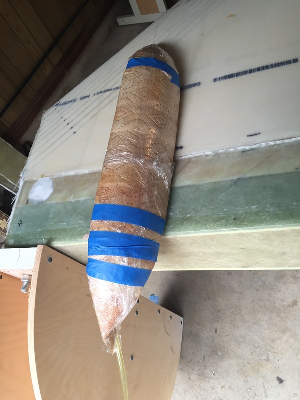
Same "3D printed Plug" (note that it's printed in 3 pieces so it can be fit to the slight curvature of the fuselage), but this time it's covered in palette wrap and ready for glassing in place (per plans)
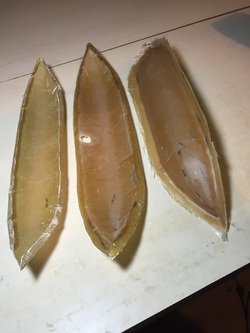
Left: Vacuum formed sump with inner flange = 125 grams
Middle: Hand layup sump on fuselage/strake with external flange = 148 grams
Right = Hand layup sump for other side prior to flange trim and drain access hole cut.
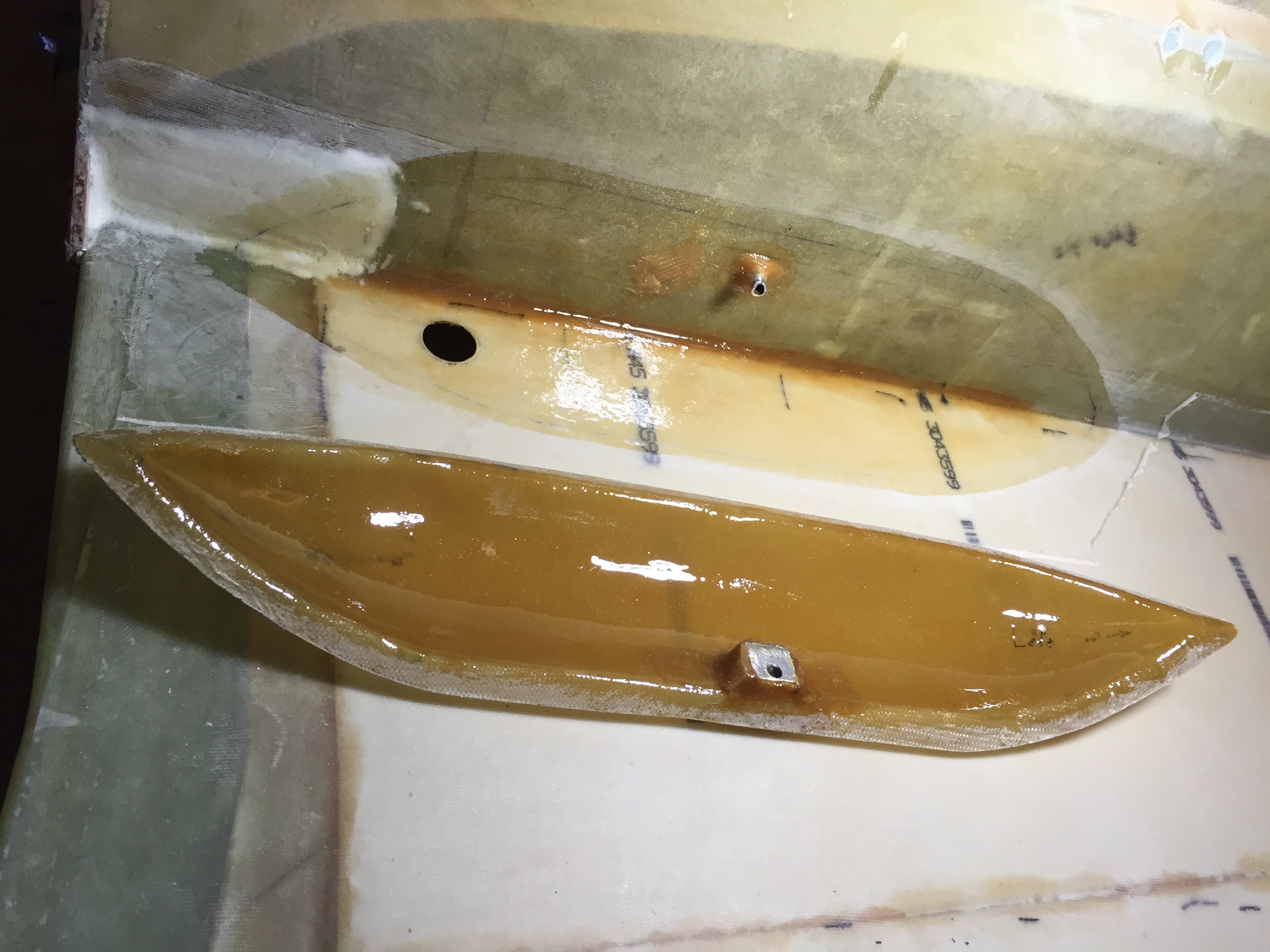
Here's a look just before flox and taping one of the side sumps on (with fuselage upside down). Note the coating of EZ Poxy over all surfaces that will see fuel. the drain hard point is seen in the sump blister, and the fuel line from the side sump to the common sump can be seen floxed and glassed in the side of the fuselage. The white area to the left is urethane foam fill of the depression below the fuselage/spar interface (micro/1 BID MGS).
|
|
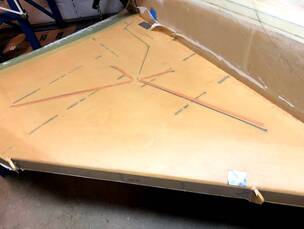
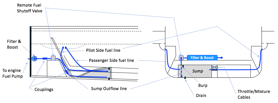
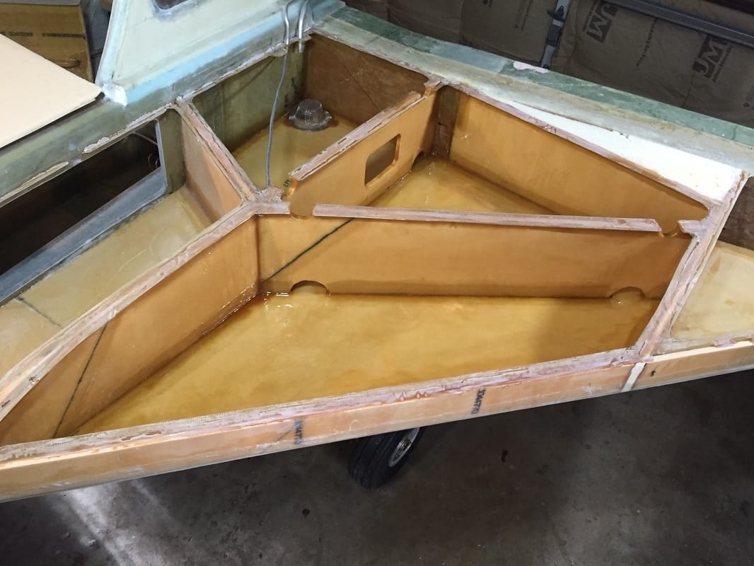
Common or Center Sump: Some builders are calling this a Header Tank, but although it's gravity fed from both side strake sumps, it's output to the engine must be pumped. Hence, I'm calling it a common sump or the "Center Sump". Here's a diagram for the fuel line scheme I'm using. This center sump also functions as the Right Rear Thigh support and I shaped it using a similar but slightly longer and taller profile. However, back seat passenger hips are no higher than with the plans thigh supports. I'm using the T-hat method for the upper curved surface so that I can glass and seal the sump to the floor and then put the top on with lots of sealing surface as is being done in the Strake Fuel Tanks. Everything is being done in EZ-Poxy for fuel resistance.
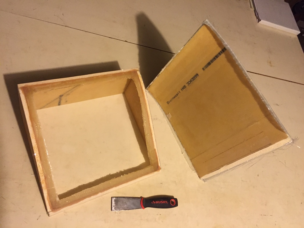
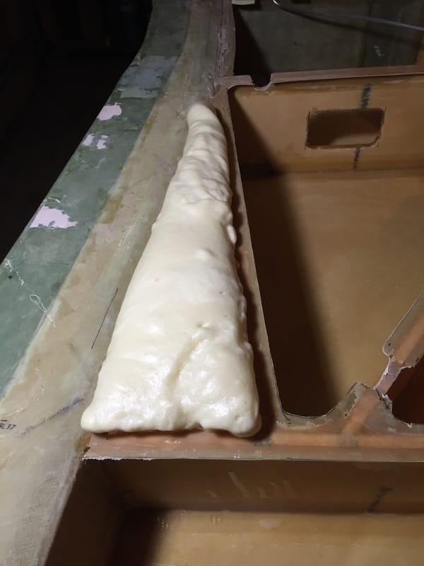
Once I had created the T-hat like flanges for the top as shown to the right, I flipped the assembly over and glassed the top of the thigh support with 2BID and 1 UNI after micro-ing all the foam slits. This was done because this top skin is already temporarily stuck to the side frame in the right snap. Once cured it's strong enough to pry off of the sides as shown leaving the nice T-flanges for later blind seal of this center sump. Note that prying the top off takes patience because it's a tight fit even with the packing tape properly applied for release. Gentle use of sharp putty knife under both the exterior and interior seams all the way around generated a pop-off after about 20 minutes. Be patient. Next I bent the tubing for the inlets from each side sump and marked where they would insert into the sides of the center sump and drilled the holes for them. Then the exit hole in the back was drilled and incremental bending of this tube was done as shown in the figure below. You can see the drain hole and "dip" starting to be contoured just below the end of the fuel exit tube (in the forward corner of the center sump, which will be the lowest point). Now ready to complete the side sumps... Jump back up to previous section (see Completion Step) 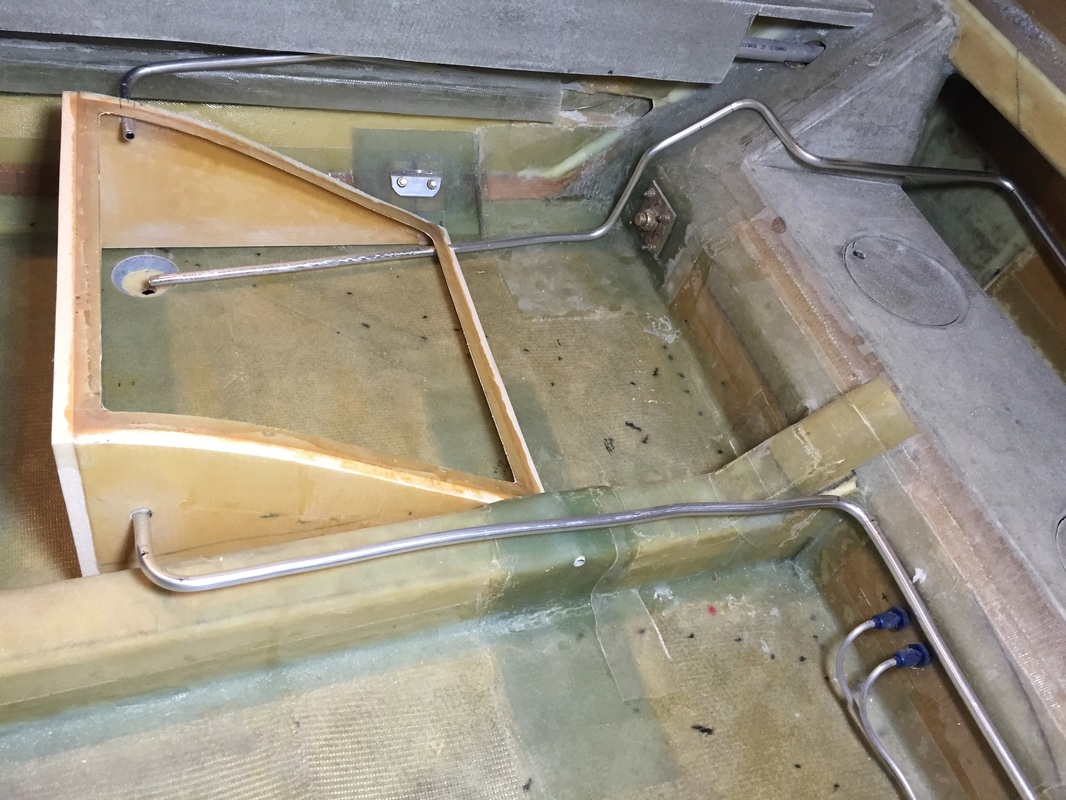
Bending the inlet tubes and outlet tube and fitting them in the appropriate holes in the sides and back of the center sump (nothing floxed or glassed yet).
|
Flox corner, 2 BID tape and Peel Ply inside seams of Common Sump/Thigh Support. Weights applied to press the cover (on the bottom) up into the contour of the side panels. Note that the cover has been packing taped, so it will be removed after cure for "T-hat" style flanges for later permanent cover installation (after the sides have been taped and sealed onto the back seat floor. There are sand bags under the cover to allow it to bend smoothly as well.
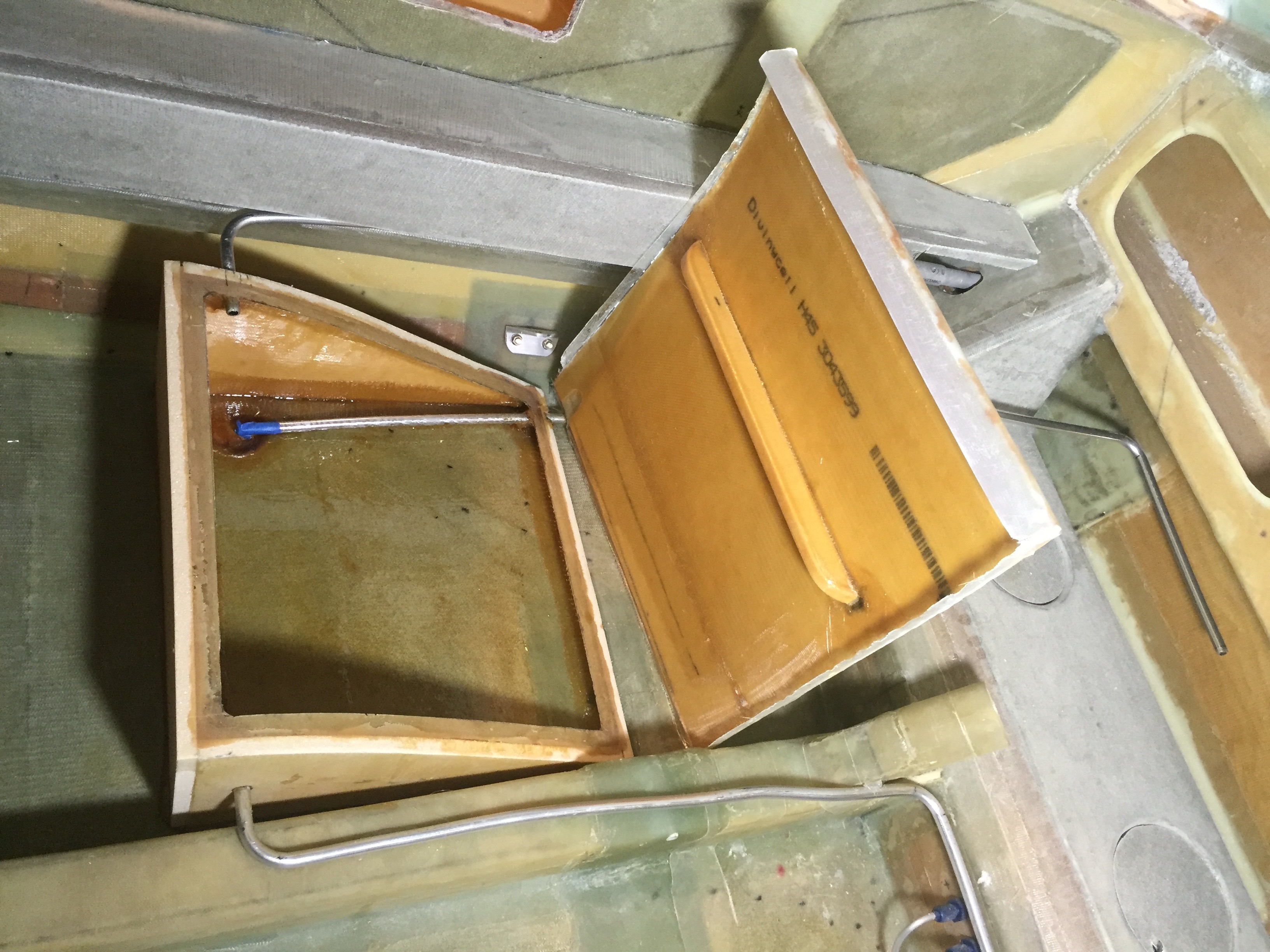
Pop off the shaped and cured top skin and trim the T-hats formed from previous picture.
Not quite done with this, but pretty close: top has 3 UNI and 1 BID plies on the interior skin and 3 BID exterior skin. All interior has been taped and coated with EZ Poxy, and I added a stiffener in the top just to be safe. Drain area is tapered, glassed and floxed, but I still have to drill and glass in the drain hard point, all fuel lines in and out are floxed and glassed. Still need to build in the burp hard point and set screw in the top as well... After side tanks are pressure tested, I'll seal this central tank and test them all together.
|
|
Vents and finishing out the Strake Interior:
I've got the vent lines installed and floxed in. Since I have lots of firewall work still to do, including the thermal blanket and aluminum shield, I'm just running the lines to the top of the firewall and taping them together. These ends will be the connection when I do the tank seal and pressure testing. Note that I've built the little plenum block to equalize pressure between the vent lines at this high point on the firewall that Buly and Bernie (and possibly others) have done. NOTE: The plans vent in the middle of the tank should be augmented with an additional vent line in the back corner. I didn't do this at this stage because I was trying to minimize deviations from the plans and wanted to minimize perforations into the tank. You need this extra vent only when you fill the tanks beyond about 60% and lower the nose on a warm ramp. In this case the plans vent gets submerged in the fuel and as the air in the tank expands it pushes fuel through the plans vent out onto the ground. The extra rear vent is a well known plans modification, and I should have done it here (while it would have been really easy to get to and seal. It was much harder to install after Phase I testing, when I had to cut into the turtleback fairing for access. Install all the vents at this stage of the build. This stage has lots of small details to be worked and some are quite mundane so I won't illustrate them, but I'll try to list them all. Things like shaping the little slot areas where vent lines come through the top skin and handling the fuel probes with hard points and perforations in the top skin and fuselage "T-hat flanges" take time, and once I've got them completed, I'll spend some time organizing and documenting the most interesting parts here. I also had my first experience with pour foam filling in the triangle between the tanks and the spar per plans. Cool stuff. It cures harder than "Great Stuff" from can, and I wish I'd used it back on my turtleback, BUT it is really sticky and you really don't want to touch it until it cures. To finish, just hacksaw blade to rough shape and sand. No problem. |
Pour Foam after expansion: Just cut the top flush with hacksaw blade, sand, and you are ready to go. I like this stuff.
|
|
Fuel Caps:
At the recommendation of Doug Pitzer, when I visited him and Bernie this summer, I'm installing the fuel caps before putting the top skin on. The reason for this is to avoid having any debris fall in the fuel tanks once I've put the top skin on. Cleaning out such debris once the skin is on will be extremely difficult. First I selected positions for the caps by lining up the cap location with best possible view through the window in B33 towards my tank drain/screen and fuel probe tip. It's not a great line of sight even in the best case, because the view angle is very shallow through the actual cap. A small mirror on stick should make the view just fine though. I'm also insuring that the cap is clear of the DB (Diagonal Baffle). With these measurements (for my strakes it's 18.75" forward of aft edge of spar, and 24 inches outboard of the longeron) I marked the top skins, cut, and fit these. I used the Dremel with router head to recess the foam the 1/8" thickness of the flange, so that it will sit flush and the outter skin glass will come over it nicely (see Part III when I put outter glass on). |
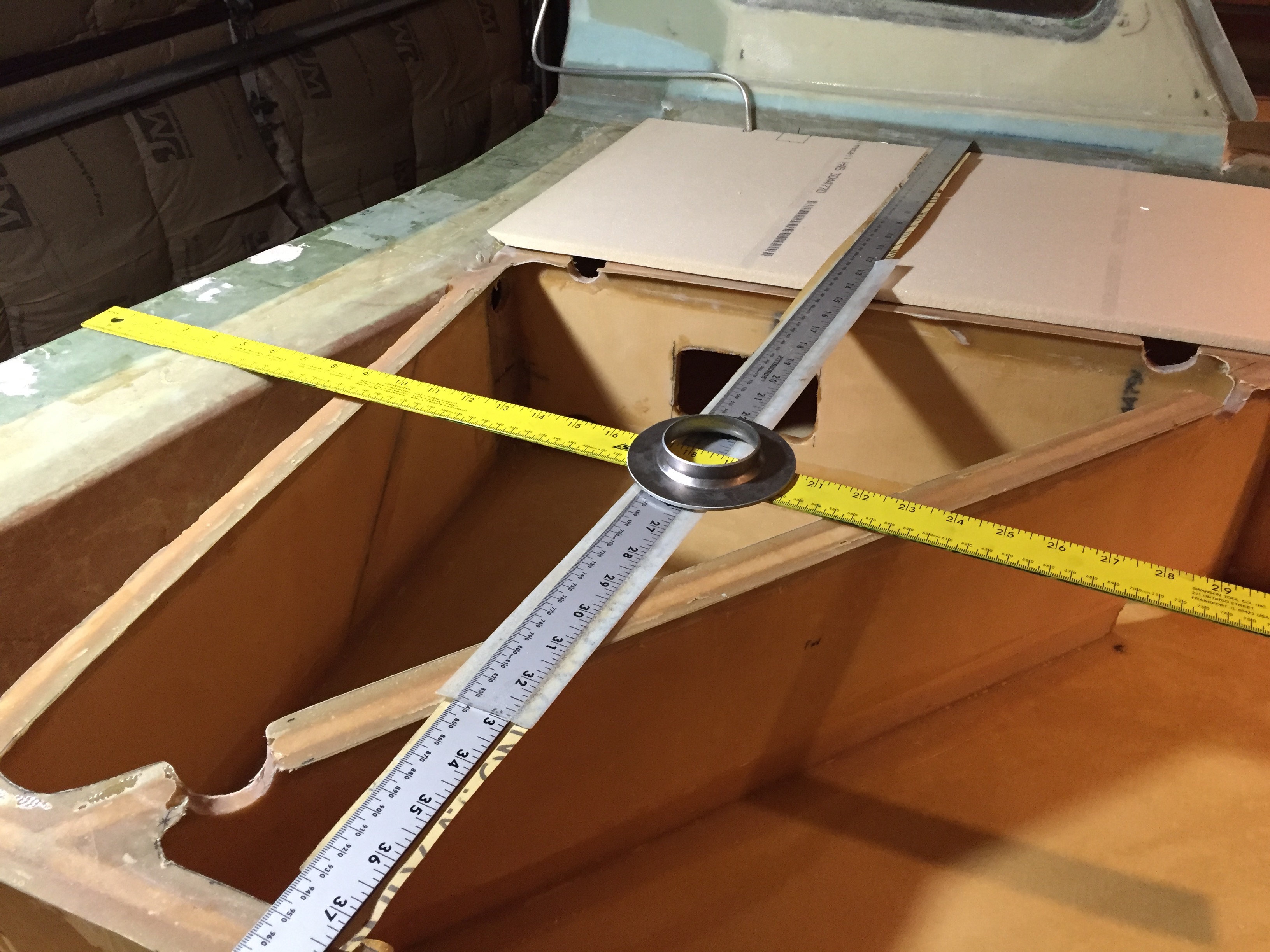
Selecting fuel fill cap location and taking measurements to transfer to outboard top skin
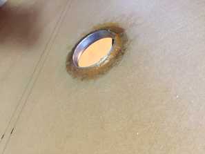
Fuel Filler cap, floxed inside and out to the top skin.
|
|
Final Sealing of strake tanks before top skin bonding: With the side sumps glassed on and the fuselage again right side up, I can do the final sealing and preparing process for bonding the top skin on. I followed the plans with additional tips from others and took the following steps on both sides: - check all the glass tape areas around the inside of the strakes inside (bottom skin, ribs, LE and strake/spar seams, T-hats) to insure no lifted glass edges. - EZ Poxy flox any rough corners with 1/2" radius fillet - Glass 2BID over the B33 seam under the 1/2 rounds in B33 to eliminate this seam as a potential leak path (use some flox in the 1/2 round corners also to assist with seal) - Drill, flox, and glass in hard points for forward fuel drain valves (using dummy 1/8 NPT plug in the hard point) - 4 BID patch over the inboard wing bolt access hole in the spar (seals spar interior from strake fuel tank) - carefuly sand and re-coat with EZ Poxy the 1/2 rounds and the rectangular window in B33 as the following coatings are applied: - sand any lifted tape edges and re-seal with EZ Poxy (no lifted areas were less than 1 inch from an actual seam area and were quite small, so no structural problems were found) - skuff the whole tank area with 36 grit sand paper and apply 2 coats of EZ Poxy (full cure and sanding between each) - touch up areas with blemeshishs after sanding (note that these EZ Poxy coatings included the tank areas on the inside of the top skins NOTE: I didn't do this, but heard about it a couple of years later from David Orr and I probably would have if I'd known: After building about 7 Long EZs, Dave Ronneberg, instead of just lapping the epoxy liberally all over the inside of the tanks, added a complete layer of 4 oz model airplane cloth because it seems to resist pin holes...inherent in the BID we use. So many people have pin hole leaks after they are finished. I didn't get any pinhole problems by the 2nd coat, but Dave's method is probably lighter overall. I can't emphasize enough how carefully I examined the fuel tank areas after each EZ Poxy coating. It seamed like I always saw some little imperfection, but they definitely seemed to go away in the 3rd spot coatings I did. I was very dilligent about vacuuming the tanks and wiping them out with a wrag before each coating, but found it really hard to insure they were spec free. I was quite liberal with the EZ Poxy brushing it on, and it appeared that the sides (vertical surfaces) were not as succeptable to blemishes as the bottom/horizontal surfaces. I was also careful to coat the bottoms and corners of the 1/2 rounds as these seemed to be good nooks for a leak to start. I would recommend floxing nice fillets in these at the inside skin corner interfaces, to reduce this hazard, prior to coating with EZ Poxy. All my work in this preparation was with fuel resistant EZ Poxy and slow 87 hardener. On the top skins I also applied 2BID along the B33 seam and let is cure (making the top skin a single piece - see photo to right) before the bonding described in the next section of Strake Work documented in Strakes Part III page (see the Chapters menu). |
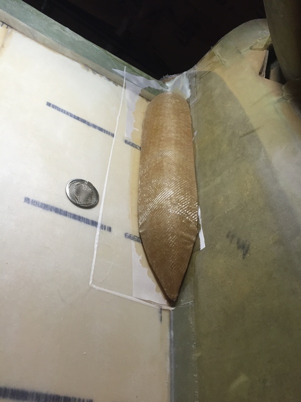
First coat of EZ-Poxy on interior of strake tanks. Note the screen has been floxed in place over the tank exit to it's sump.
Top Skins bonded along the B33 edge and getting their tank areas coated with EZ Poxy too. Note the filler cap flanges.
|