Chapter 27.1: MORE Phase I Testing Stuff
Started another page to describe other activity during the Phase I testing process
|
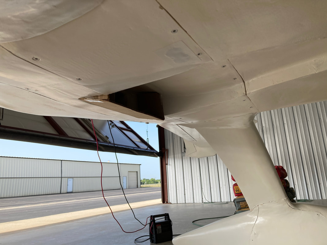
Finishing the Wing/Spar/Strake Seams:
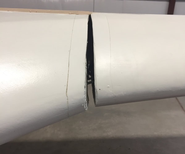
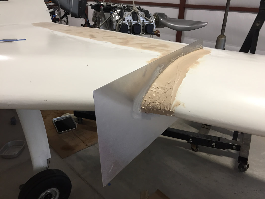
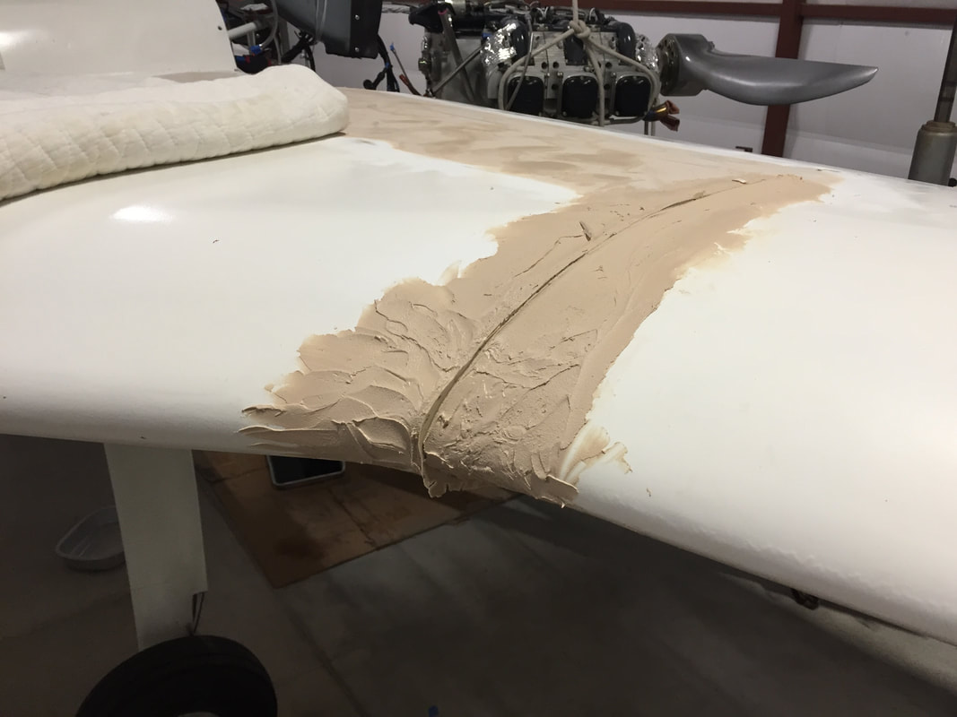
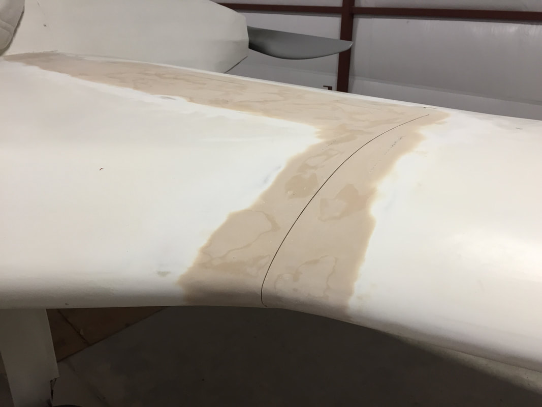
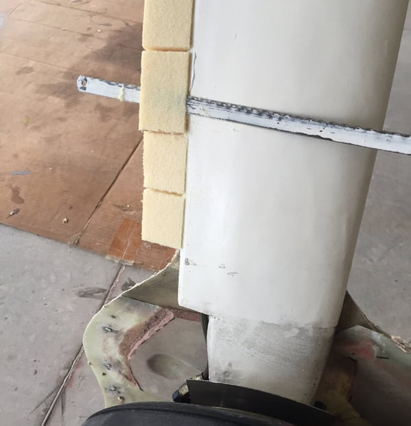
I did not do detailed seam finishing between the wings and the spar or the strakes prior to Ph I testing, as I wanted to make sure that I didn't have to remove the wing and make any adjustments based on flight characteristics. After 20 hrs of flight tests, it's clear that the wing setting is great and during this early flight testing I simply taped over these seams with 3" wide Vinyl tap (3M). The tape was fine but it was starting to split in a couple of places. For the wing/spar seam: I used a 4 ply BID tape to bridge the gap and left a reference 1/8" hole at the outboard end. With a laser I can if needed in the future, mark the cut line for this seam between the spar and the wing if I need to remove the wing. For the wing/strake seam: it was a little more complicated, as this is a 3 dimensional seam. I used the same method Bernie Siu and others have used in the following steps: 1. Use small blue foam strips to insure that antenna cables are up and away from the seam (can't be damaged in later seam cutting, and plate insertion) 2. Two BID tape bridging the gaps (which were as large as 3/4" on the leading edges) and cure. This provided a reasonably smooth and continuous surface for later filling and smoothing as described below. 3. Laser mark the cut line (aligned with the inboard edge of the wing) with a fine tooth multi-tool (Fein Tool) 4. Slide a 1mm thick clean smooth Aluminum plate (that has a gap cut to accommodate the antenna cables (see picture) and has been coated with car paste wax so epoxy won't stick to it) into the the slit made in step 3. 5. Build up West/410 filler on both sides of the Aluminum plate to form the start point for shaping this seam 6. Slide the Aluminum plate back out after the fill has cured. This requires a hammer and a wood block against the aft edges of the Aluminum plate on the top and bottom - and you need to be careful/patient to let the wax work in breaking the slight seal between the epoxy fill and the plate. 7. Sand to shape the fill (I needed a 2nd fill to get this the way I wanted it) for a nice wing/strake transition 8. Primer coat (I ousted rolled same Southern Polyurethane Epoxy Primer used on the rest of the plane) to protect the fill. 9. Vinyl electrical tape over the 1 mm remaining seem in this smooth transition zone. 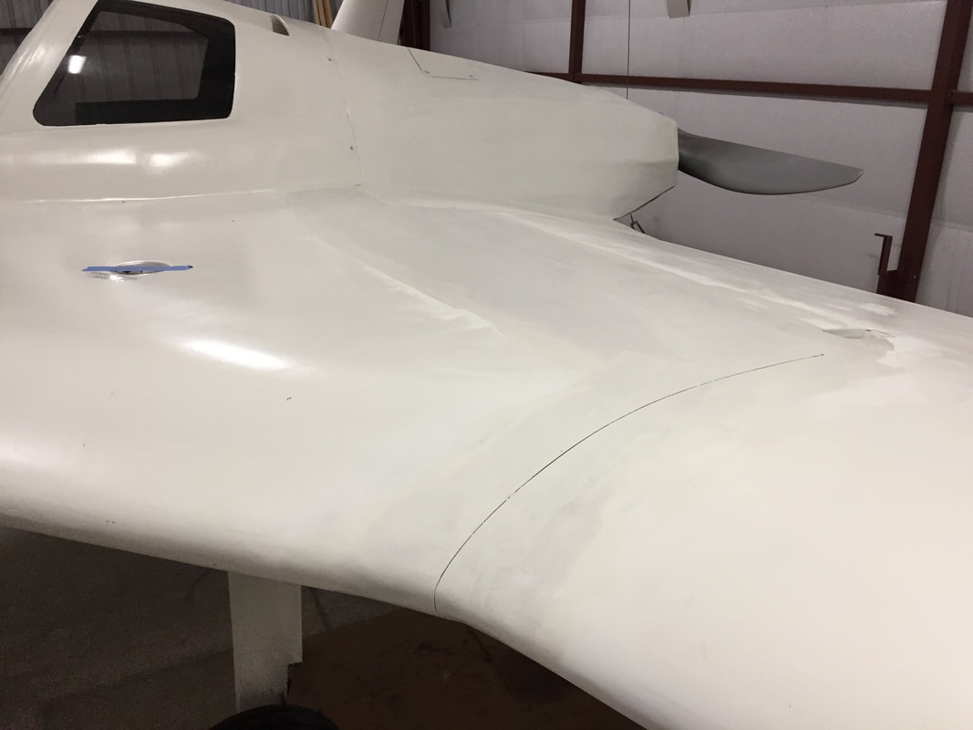
|
|
|
Replacement of Alternator Stator:
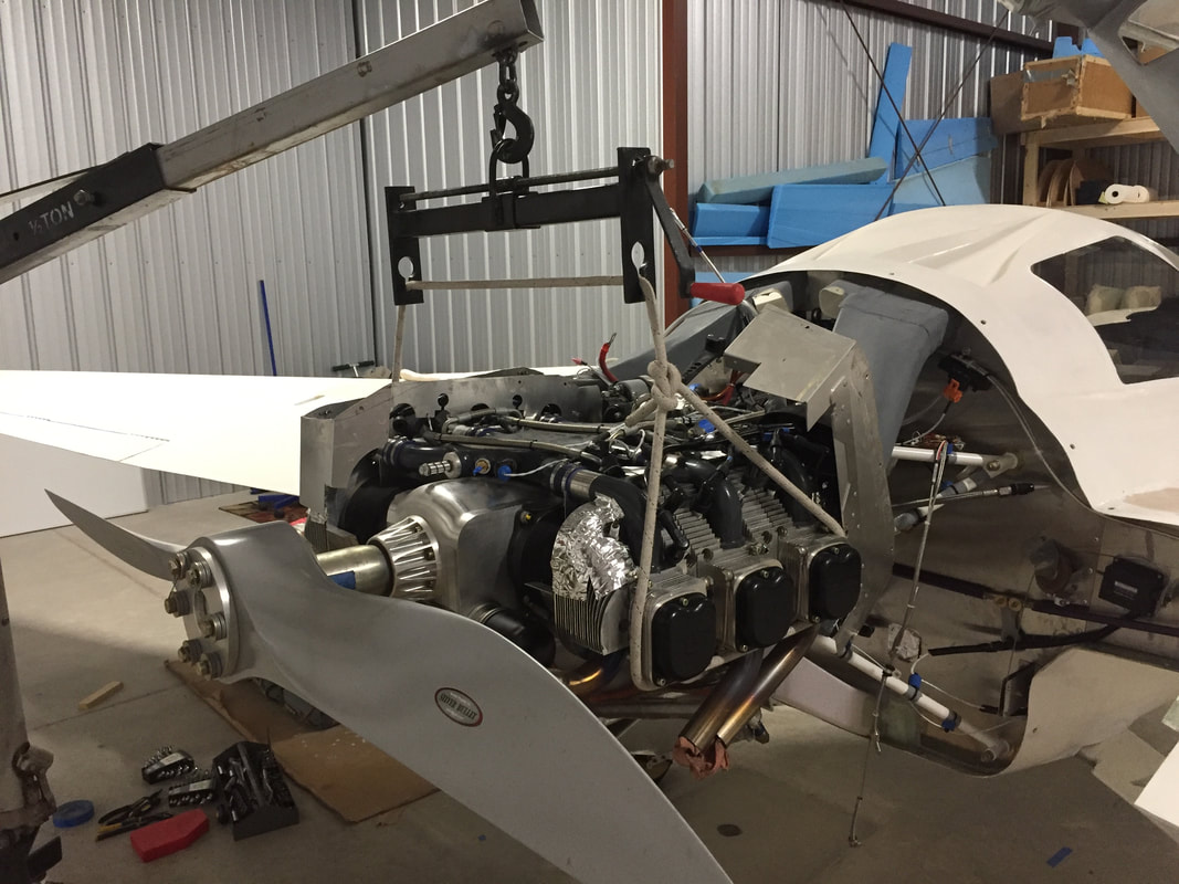
During Flight Test 32 I began to notice bus voltage in the range of 12.6V vs the 14V I had seen in the past. In troubleshooting this, I eventually found that one of the bolts holding the throttle bracket in place on the engine had worked loose and dropped into the alternator housing and likely damaged the alternator in some way. I talked with UL and they were 90% sure that there was a problem with the stator, as I was not the first to report this exact problem. They sent me the special tool to hold the forward flange of the crankshaft and a puller for extracting the rotor cup before accessing the stator for inspection. None of this could be done without removing he engine from it's mount however, due to the closeness of the starter ring to the mount, which has to come off first. So, I went about disconnecting everything needed to pull the motor back about 15 inches to give me the clearance to work on the alternator. It took me about 3 hrs of prep to remove the engine with a lift and stabilize it on a bench. Cracking loose the crank flange bolt to get the rotor off was a 2 person job requiring ~250 ftlbs of torque in the correct direction and we used 2 breaker bars (one with a 3/4" drive interface to the crank flange tool, and the other a 1/2" drive 30mm socket for the bolt (which is Red Locktite secure). The instructions are very clear on all this, but the big thing you need is the right length M6 bolts to attach the special tool to the rotor cup (which is connected to the crank flange) so the bolts don't protrude and damage the stator windings. This warning should be in the instructions and are not. Thankfully I could feel this problem and the only damage done was on the already damaged stator... I had the right size M6x11 bolts for assembly with the new stator, which was an easy order from Wicks, who carry UL replacement parts. It took another 3 hrs to reconnect and mount the engine. Ground test and later flight test showed the charging system back to great performance 14.1 solid bus voltage and decaying charge current to ~1 Amp in about 8 minutes while taxing out to runway. Some pictures provided here. This engine removal and re-installation turned out to not be a big time sink, and gave me more confidence overall in the serviceability of the engine with the experience. New stator was just what was needed. Charging system is working great again. 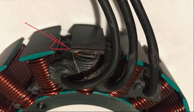
Burn marks on shorted stator winding
|
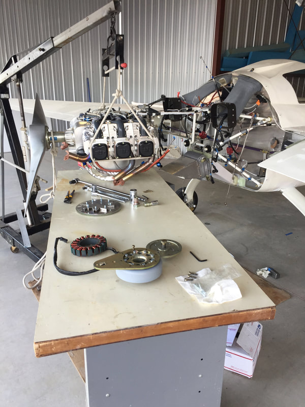
FOREGROUND: Stator, Grey rotor with crank flange and removal tool attached, round puller plate with central pusher bolt for removing the rotor.
MID TABLE: wrench and breaker bar and socket and 30 mm crankshaft bolt, and starter sprocket/fan.
FAR END: lift supported engine fully removed from mount
|
|
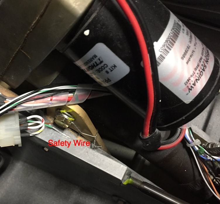
Safety Wiring Nosegear Actuator Mount Bolts:
I'd been warned to keep an eye on the bolts that hold the Wilhelmson Nosegear actuator to the cheek plates in NG30 as I started to fly, and indeed my bolts were loosening a little about every other flight. The Cozy Builders group has a thread on this and Jack Wilhelmson had devised an improved lock watering system, which I bought from him. However, when I received it, I just didn't have the confidence I wanted that it was going to work, and an A&P friend of mine suggested I just safety wire them. So I ordered the two AN5H-12 drilled bolts and safety wired them to the slightly exposed lightening holes in the cheek plates. I'll still keep an eye on them for a while, but this seems to be a comforting fix. |
|
CHT Tailoring:
As summer temps rose into the 90s (and they will get to 100) I started to notice more restriction of climbing rate at full power due to both Oil temperatures and the center cylinder CHT's (#'s 3&4). At cruise I'm not having any problems, and in fact at 4000+ ft the OAT is often low 70's F which easily cools my engine running at cruise RPM's of 2500. I will continue examining this, but still working out what I want to implement so that I don't overcool in cruise conditions. The improvement I've made that really helped was to insert a small deflector inside the air plenum above each bank of cylinders that increases the pressure over the middle cylinders (#3 nd #4) to bias flow here since these cylinders run about 30F hotter than the front and rear cylinders. I've verified the improvement on the even cylinder side and am awaiting good weather to test the other side as well. I'll show a before/after comparison of the temperatures when this is completed.
As summer temps rose into the 90s (and they will get to 100) I started to notice more restriction of climbing rate at full power due to both Oil temperatures and the center cylinder CHT's (#'s 3&4). At cruise I'm not having any problems, and in fact at 4000+ ft the OAT is often low 70's F which easily cools my engine running at cruise RPM's of 2500. I will continue examining this, but still working out what I want to implement so that I don't overcool in cruise conditions. The improvement I've made that really helped was to insert a small deflector inside the air plenum above each bank of cylinders that increases the pressure over the middle cylinders (#3 nd #4) to bias flow here since these cylinders run about 30F hotter than the front and rear cylinders. I've verified the improvement on the even cylinder side and am awaiting good weather to test the other side as well. I'll show a before/after comparison of the temperatures when this is completed.
|
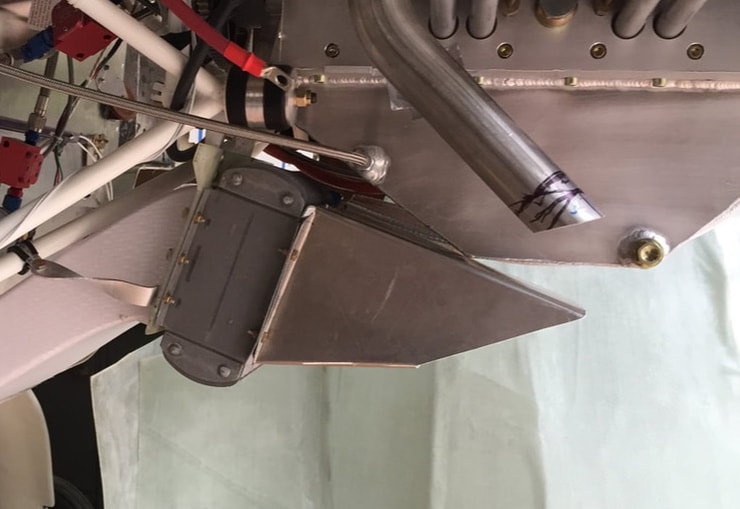
Oil Cooling:
Like the CHT's the Oil temperatures can grow to 220F+ in full power climb in the summer. I know I can greatly improve the diffuser aft of the oil cooler. Absolutely no problem cooling the oil at all cruise conditions other than WOT. I designed an improved diffuser with a curved upper boundary that better followed the profile available under the engine oil pan, and also opened up the bottom boundary significantly so that there's no restriction of flow aft of the cooler itself. Installation required cutting the exit hole bigger in the lower cowling and then re-glassing the cowling to "fit". Results are better for sure, but I can still push the oil temperatures to the high 220's F in a full power climb out with OAT's in the mid 90'sF before I start pulling the throttle back (I'm typically 2000' AGL at this point). Note that the max oil temp recommended is 248F. So next I'm looking at improvement of the inlet scoop. I'd reduced the belly NACA scoop early on to match the sectional area of the cooler, which I still think was OK, but I'm getting separation in the scoop at the main gear cover and I think most of the high energy flow is missing the lip of the actual scoop further back. My plan is to come forward and down with this scoop lip so that the area being captured is closer to the actual area of the cooler AND reach about 0.5" below the contour of the bottom of the fuselage to insure I'm getting some high velocity air. I've implemented this scoop increase but not seeing a big improvement in cooling in one short test flight. The scoop is creating more separation behind it of course so there is a little drag penalty with it. I'll run more tests and eventually decide wether to reduce the scoop lip a little and close off the exhaust opening (now that it's better streamlined with the underside of the oil pan). For now (heat of Summer) I think it's a good trade to have the additional pressure drop across the cooler, and have already gotten better at climbing at more moderate power settings to prevent over-temp in the oil system. I later returned to the Belly NACA inlet to reduce drag and this work is discussed here in Post Ph I improvements. |
Here I've built a cardboard mockup of the scoop extension to see how it fits. The idea is to have the scoop follow the depth profile of the "floor" of the NACA scoop forward, and you can see that it looks like my NACA should probably be deeper at the back of the gear cover. It's built to plans, so I'm going to have the lip come down 1/2" to catch more high energy flow up into the oil cooler duct.
|
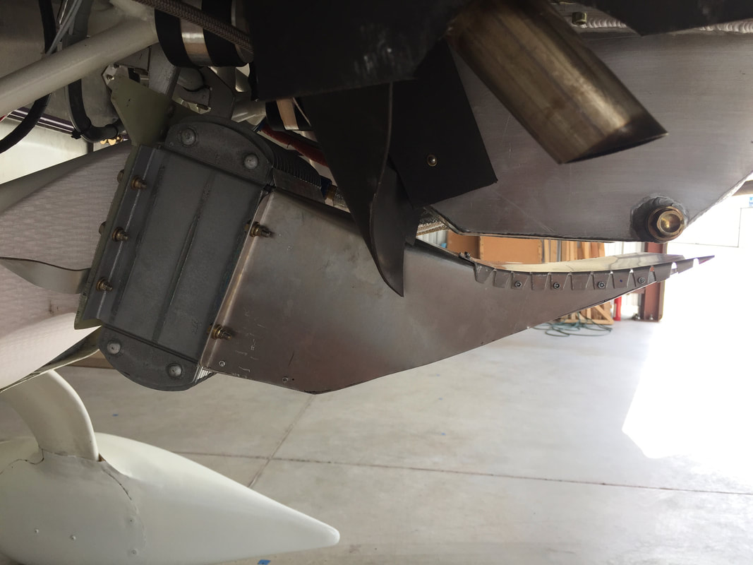
Main Gear Leg Fairings:
As I get closer to finishing Ph I testing I want to complete several small drag reduction tasks and fly them to evaluate any changes in performance. Two that are now ready to complete since I have the wheel pants done are cleaning up the trailing edge of the main gear fairing and making fairings for the gear leg/fuselage interface. I'll show some of the work on these here.
Gear Leg Trailing Edge (TE) Fairing: The TE of the main gear is almost 1/2" thick and rounded and the shape of the gear leg profile in the last 1/3 of the chord is not very aerodynamic (particularly on the underside). Many Cozy builders have purchased a fairing kit which has a nice zero lift airfoil shape in foam that you fit over the gear leg and glass. I didn't want to do this because I didn't want to increase the thickness of the gear leg foil profile (more drag) and wanted to keep the chord length from growing commensurate with this thickness. So I just looked at how to extend the profile from the TE and fair the foil profile only in the last 40% to reduce drag. Here I show pictorial snapshots of key progress on this.
Micro'd little blocks of urethane foam to TE of the gear leg then cut them with hacksaw aligned with the aft taper of the gear leg on the outside and inside surfaces (which produced a sharp TE shape in the foam)
|
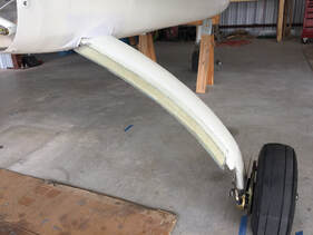
2 BID glass top and bottom overlapping 1" onto the gear leg
|
A couple of passes of fill and sanding later gives a very nice foil shape for the gear leg. Will primer when all fairing is done...
|
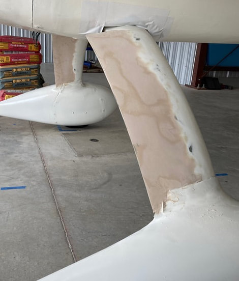
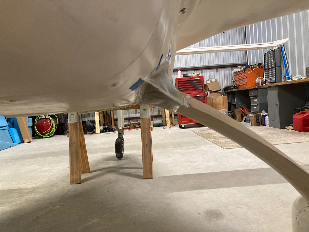
Gear Leg/Fuselage Fairing: I also needed to address the big holes where the gear leg comes out of the fuselage, which I'd only taped over during the first part of Phase I. With the gear leg TE profile done, I could now build a fairing with the fuselage to match it. I used clay to form the 3D fillet shape, following the method used by Bernie Siu, but mine ended up a little bit bigger. There's no great guidance on size here, so I just used my eye and some experience in intersection drag reduction from the beginning of my career doing similar things for the Navy. Getting all the packing tape between the clay and the gear leg and the clay and the fuselage, and using pallet wrap between the clay and the new layup also takes a while and the latter does prevent having as smooth a contact with the clay as you might like, but it enables getting the cured layup off "clean" and not having a big mess to clean up on the airplane when done with the clay.
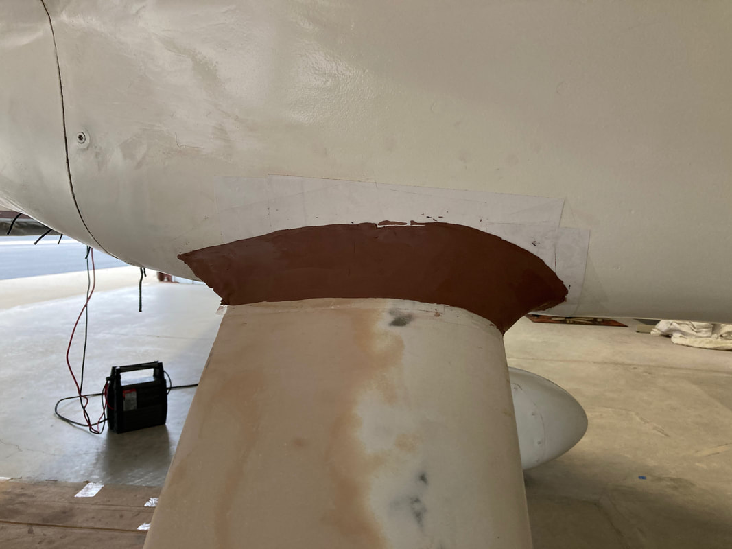
1. Clear tape everything and then apply and sculpt the clay...
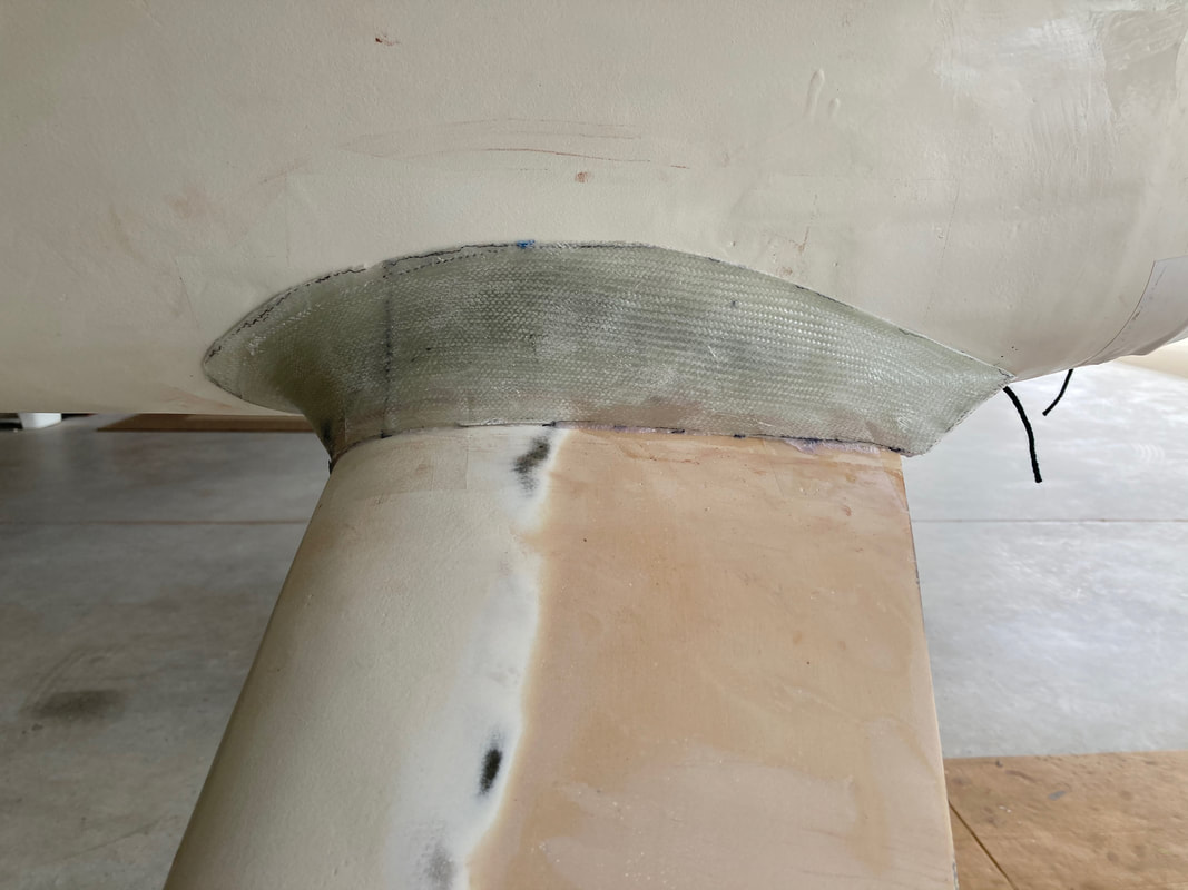
4. Glass cured, clay and tape removed, bead of flox at leg contact and fairing taped in place to let the flox cure.
|

2. three plies BID: not an easy layup process with this complex shape. Be patient.
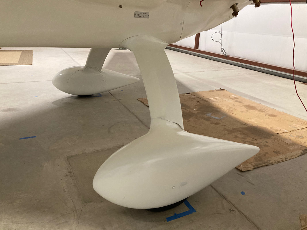
5. Getting primer on...
|
3. A look from the trailing edge...
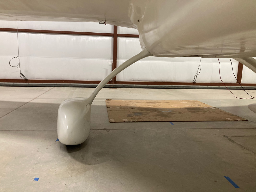
6. Front view as flown in primer
|