Fish's Cozy MKIV
  • Welcome
  • Preparation, Visits, Tips
    • Preparation
    • Visits
    • Tips and Tricks
    • Special Cases - Interesting Fixes
  • Chapters 3-15
    • Ch 3 Practice
    • Ch 4-7 Fuselage, Main Gear
    • Ch 8 Head Rest, Heat Duct, Seat Belts
    • Ch 9 Main Landing Gear
    • Ch 10-12 Canard & Elevators
    • Ch 13 Nose >
      • Ch 13.1 Nose gear, Brakes, Landing Light and Skid Plate
      • Ch 13.2 Nose Top & Canard Cover
      • Ch 13.3 Relevant Later Work
    • Ch 14 Spar
    • Ch 15 Firewall
  • Chapters 16-25
    • Ch 16 Controls
    • Ch 17 Trim
    • Ch 18 Turtleback/Canopy >
      • Ch 18.1 Turtleback
      • Ch 18.2 Canopy
      • Ch 18.3: Latch, IP Cover, Misc
      • Ch 18.4 Lift and Locking Canopy (Version 1)
      • Ch 18.5 Electric Lift Canopy (Version 2)
      • Ch 18.6 NACA's for Engine Cooling
    • Ch 19 Wings
    • Ch 20: Winglets/Rudders >
      • Ch 20.1 Winglet Fabrication
      • Ch 20.2 Winglet Attachment
      • Ch 20.3: Rudder Fabrication
    • Ch 21 Strakes >
      • Ch 21.1 Strakes: Through "Top Hats"
      • Ch 21.2 Strakes: Bottom Skin through Prep for Top Skin Final Bonding
      • Ch 21.3 Strakes: Top Skin Final Bond through Fuel Tank Seal
      • Ch 21.4 Strakes: Misc Completion of Strakes
      • Ch 21.5: Strakes: Wing/Strake Fit Check
      • Ch 21.6: Strakes: Post Cure Tanks
    • Ch 22: Electrical >
      • Ch 22.1: Electrical: Inst Panel
      • Ch 22.2: Electrical: Firewall
      • Ch 22.3: Electrical: Warning Lights
      • Ch 22.4: Phase I Testing
    • Ch 23 Engine and Cowling >
      • Ch 23.1 Firewall and Mount
      • Ch 23.2: UL 520is Initial Integration
      • Ch 23.3 Cowling
      • Ch 23.4 UL 520is First Start
    • Ch 24: Seats, Armrests, Fairings >
      • Ch 24.1: Fairings
    • Ch 25: Finishing >
      • Ch 25.1 Canard
      • Ch 25.2 Interior
      • Ch 25.3 Fuselage/Strakes Bottom
      • Ch 25.4 Fuselage/Strakes/Canopy Top
      • Ch 25.5 Wings
      • Ch 25.6 Assembly in Primer and W&B 1
  • Ch 26: Hangar
    • Ch 26.1 Assembly and Fitting
    • Ch 26.2 More Punch List Stuff
    • Ch 26.3 Inspections
  • Ch 27: Ground Tests, First Flight and Ph I Testing
    • Ch 27.1: More Ph I Testing Stuff
  • Ch 28: Post Phase I Improvements
  • Ch 28.1: More Improvements
  • Ch 29: IFR

Chapter 21.4: Strakes  (Misc Completion of Strakes)

Picture

This page picks up where Ch 21 Part III leaves off and generally deals with finishing the leading edges done and any loose ends with the Strakes Ch 21.

Fuel Probes:
    I'm using capacitive fuel probes as mentioned earlier and with the L tank sealed I could do the insertion.  This was a multi-step process because I need to be careful not to harm the 3/8" NPT threads in the probe hard point.  Here's what I did:
   - tank under 6" H2O pressure (manometer and bicycle pump)
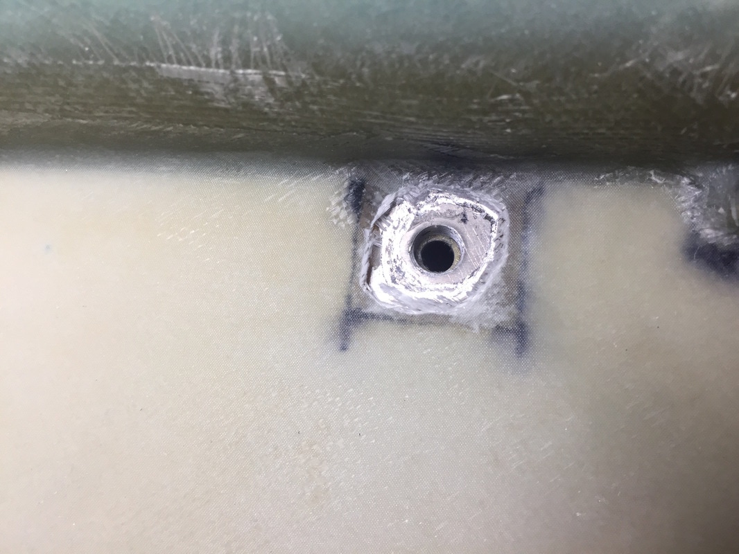
   - Dremel the top skin off of hard point (I'd masked the NPT hole before applying top skin)
   - mark the center of the hole needed through bottom skin with Sharpie fine point
   - carefully drill through the inner skin with .27" bit (careful to stay away from hard point threads).  When the bit goes through, the higher pressure air in the tank blows out carrying debris with it over about 4 seconds)
   - insert probe and make sure it threads all the way down snug
   - remove and install 3/8" NPT plug and re-pressurize (holding pressure for over a week and counting)

Note on Fuel Cap: I masked over the removable cap when I applied the top skin and Dremel trimmed it off the same way after cure
Picture
Fuel cap after removal of top skin
Picture
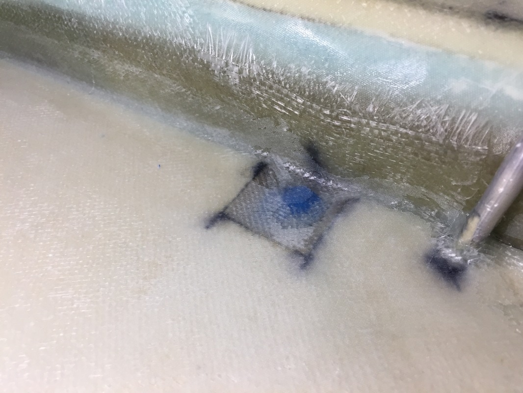
Before top skin removal over fuel probe hard point
Picture
Dremel away top skin and drill through inner skin (don't touch NPT threads!)
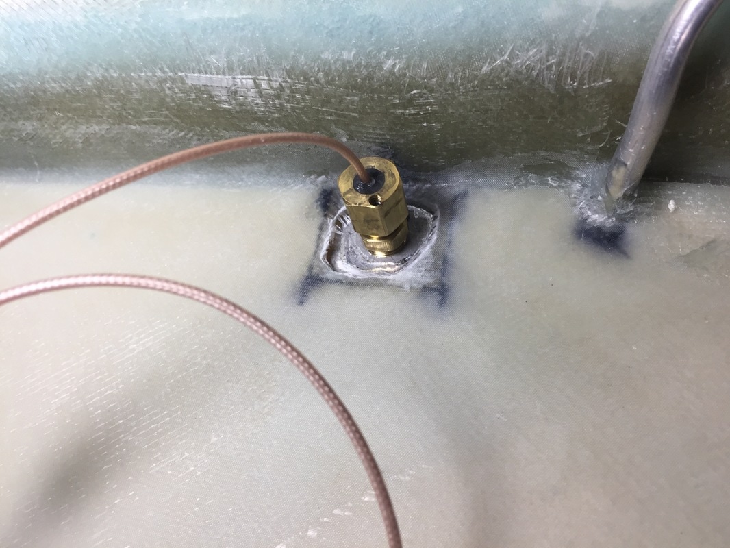
Picture
Fuel Probe fit checked

Leading Edges:
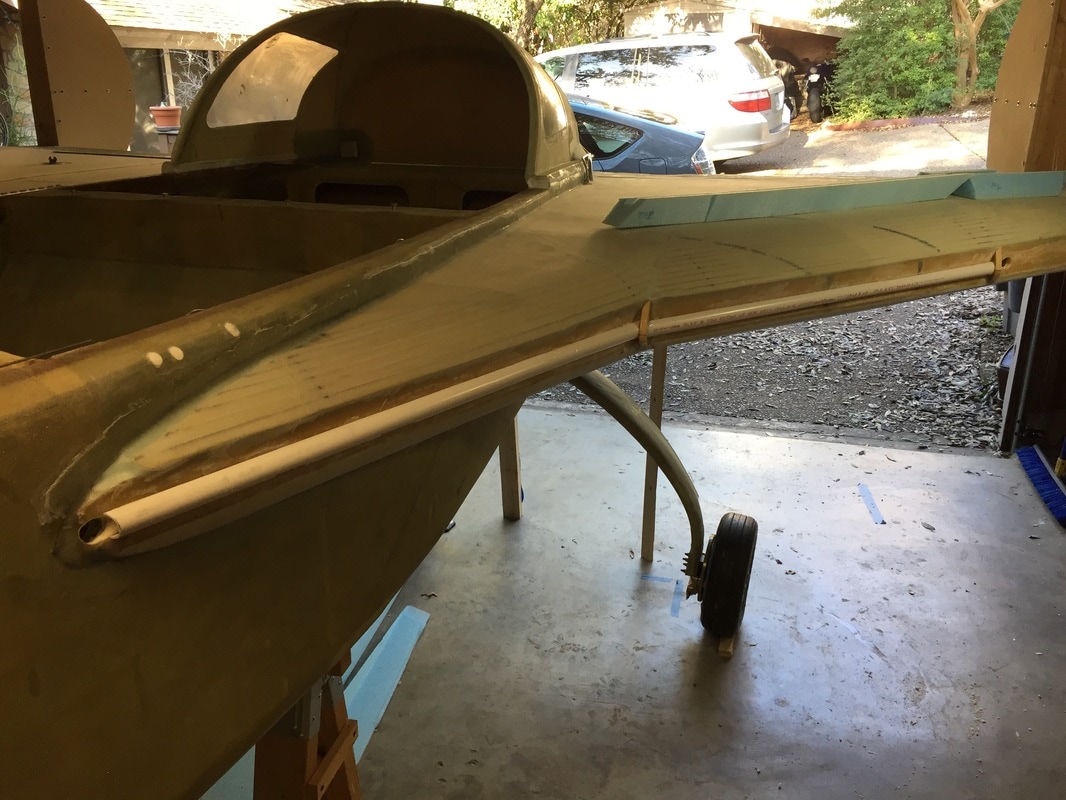
    With the L strake tank sealed and it's top skin on, I can start work on it's Leading Edge (LE).  Since my extended strakes run to just in front of the IP, I'm routing the wing antennas and Nav/Strobe cables directly through a conduit in the LE.  Here are the steps I'm using (not completed yet):
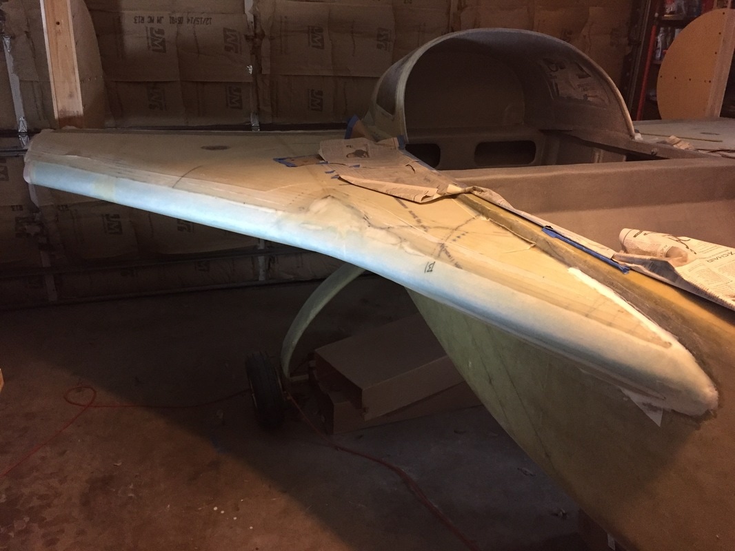
  • Clean up LE bulkhead so it can be bonded to
  • Grab the R33/R57/strake tip profiles I cut off earlier when apply the outer skins and Dremel out the "D" profile needed for the 3/4" PVC conduit discussed below.  Then bond them back in place on R33/R57/strake tip bulkheads (5 min epoxy).
  • Cut a 3/4" low pressure PVC tube, which will be the conduit inside the LE foam, to the lengths needed.  I'm using 2 lengths: one along the tank LE and one along the extended strake LE.  The wires will enter from the void space outboard of R57 and they will have connectors there for mating with their partners in the wings.
  • Cut the PVC along it's length so it's "D" shape is small enough to fit in the LE foam profile.  I did this with my Blade Runner, and a fence, but the key is holding the PVC as you cut (it wants to twist).  Don't push too hard, go slow.
  • Bond the PVC to the bulkhead using the profile tips as guides (5 min epoxy).  I also used a temporary support and duct tape to hold these in position for cure. 
  • Hot wire the blue foam for LE.  I used left over wing and winglet packaging blue foam from Eureka, and used the little tips mentioned in the first bullet above to mark how thick the blue foam would need to be, before bonding them back on the LE bulkhead.
  • Use some left over 3/4" PVC with 100 grit sand paper hot glued around it to sand out the depression in the blue foam so it will bond  flush to the LE bulkhead.  This takes a few iterations with cleaning of the sand paper as you'd expect if you've sanded blue foam.
  • Drill the access holes in LE outboard of R57 and in the fuselage where the strake LE comes in behind the IP
  • Run the cables through the conduit.  I put some soft bathtub caulk around the perimeter of these access holes to prevent chafing the cable jackets.  In my Cozy the cables run here are the shielded 3 conductor to the Nav/Strobe lights and 2 COAX cables for the wing and winglet antennas.
  • Bond (micro) the blue foam in position along the LE bulkhead
  • Shape the blue foam to the LE profiles.  I used a foam pattern for R33 offset for the skin thickness to get the nose profile close on the outer portions of the strakes, and allowed the inner (extended) strake LE be more rounded and less deep since it's pushing air more laterally than dividing high and low like a lifting surface.  I also chose to blend the transition from the extended strake to the outer strake by using pour foam to smooth the crease between them both on the upper and lower surface.  It turns out the pour foam was also valuable for blending the lower skin profile into the nose as well.  This took 4-5 sanding sessions but I'm pretty happy with how it turned out.  Remainder of smoothing will be in the finishing phase...
  • Micro to Hard Shell the foam - I learned this technique from Marc Zietlin and others here.
  • (still need to do this as of end of March 2017) Glass the LE with 2 UND tapering onto the top and bottom skin as specified in the plans
Picture
2 UNI plies at 45 degrees from LE line and PP over the blue foam...
Picture
This is what the conduit looks like bonded along with the tip profile pieces to the strake LE.
Picture
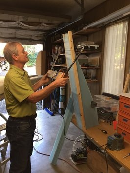
This is a staged photo just after I actually did the hot wire cut (when I could get Dianne to be photographer). It shows how I used some leftover wooden foam packing slats from ACS to guide the hot wire for cutting the piece that's leaning on the table in the background. The slats are just held in place with 3 sheetrock screws, and I put some weights on the back of this blue foam to keep it from moving while I cut it (just because it was an unusual shaped piece of left over blue foam).
Picture
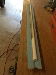
This is my PVC with sand paper conduit clearance grinding apparatus resting in the slot it's cutting in the blue foam.
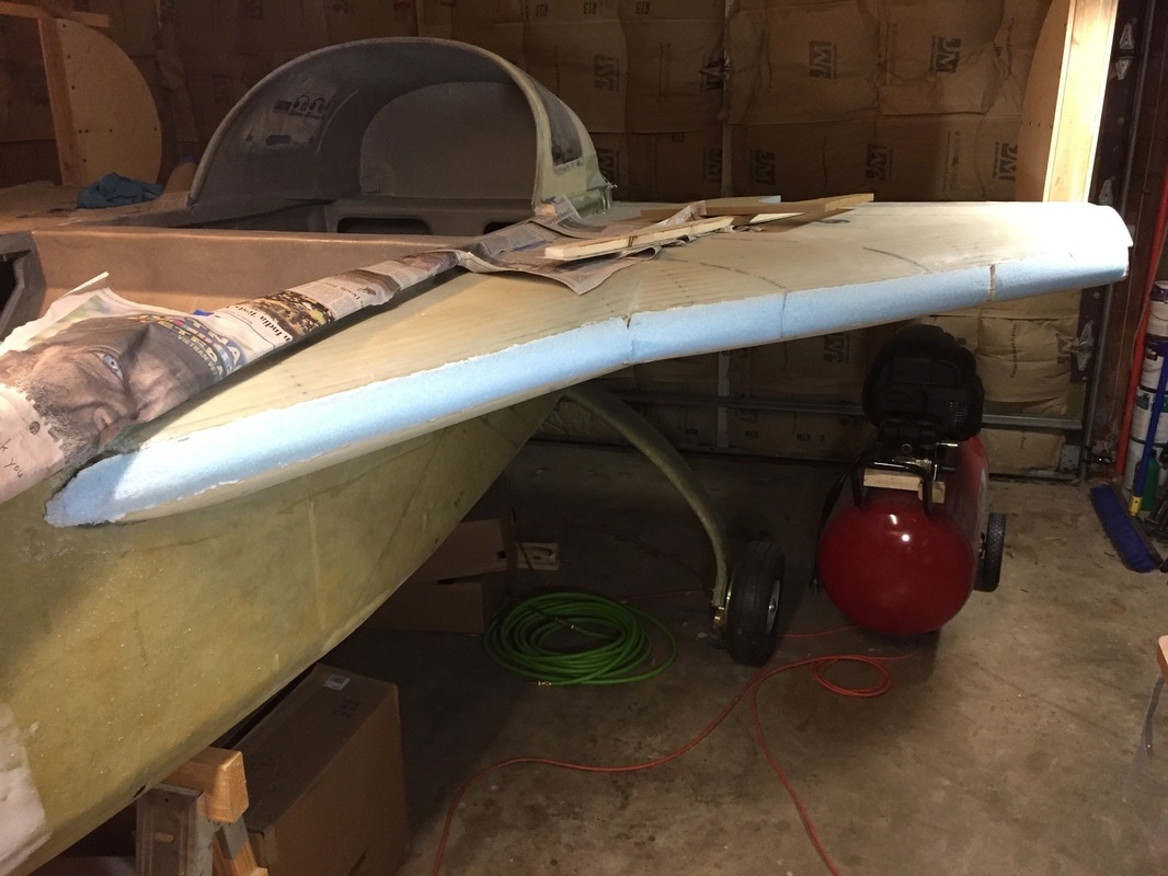
Picture
Roughing the blue foam leading edge pieces. Still some fine shaping to do...but you get the idea
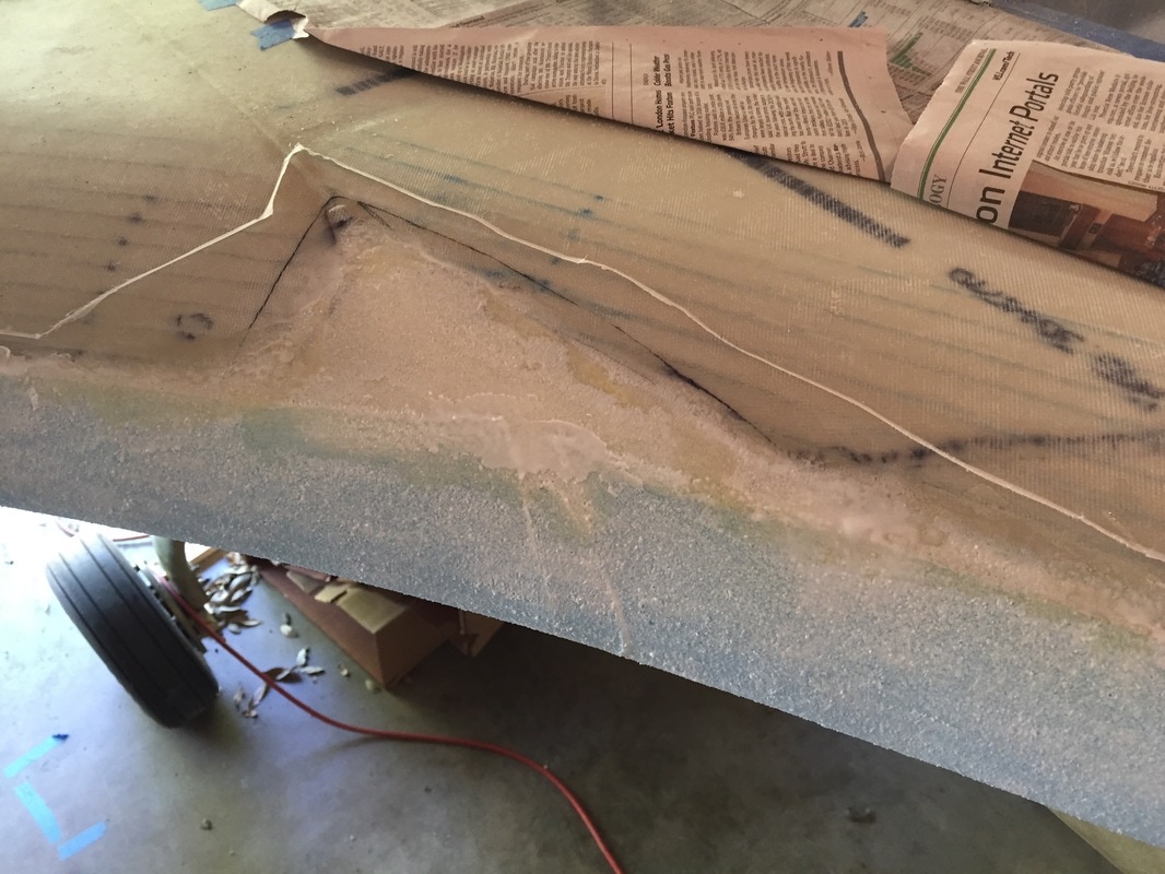
Picture
Right strake top area blending with pour foam after hard shell
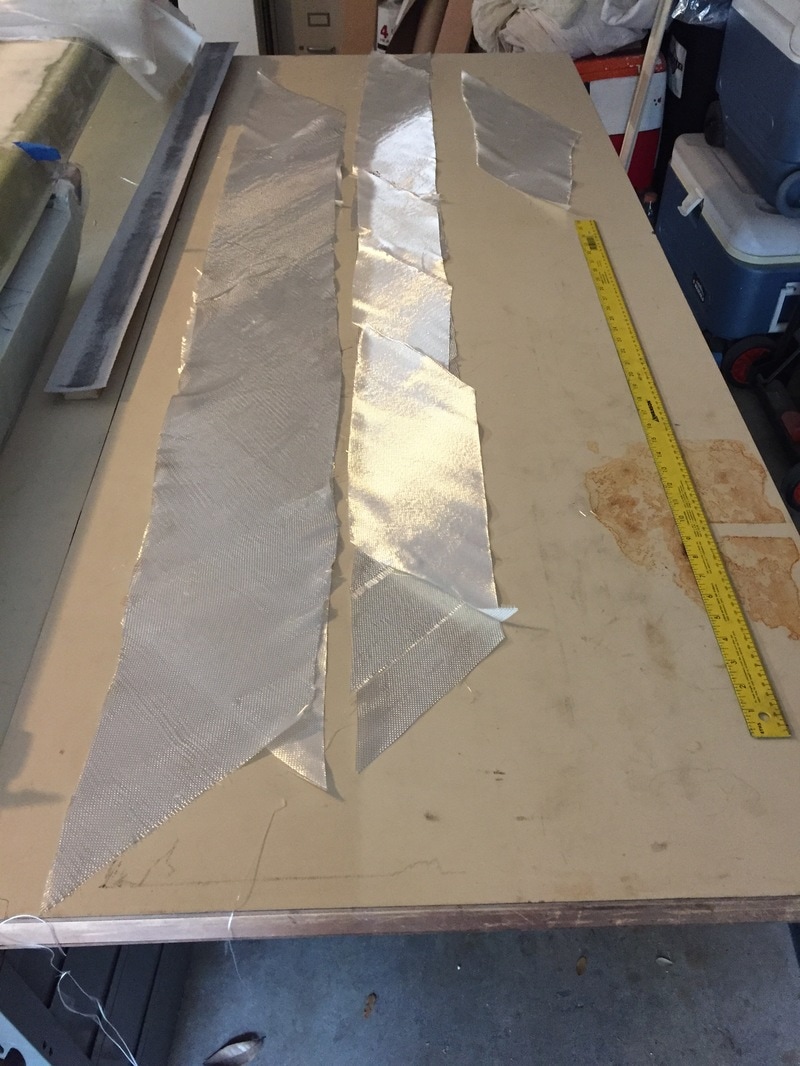
Picture
Preparation for glassing LE: Because the plans call for UNI you can butt sections together. Most of this was cut from scrap UNI from strake skins and TB. Scraps are kept rolled up and sealed in a big tub. I cut 7" long first ply and 10" long 2nd ply to get 0.75" overlap and 1.25" overlap on both the top and bottom skin everywhere except in the transition region. I had to custom measure, cut and apply in these areas.

On to Wing/Strake Fit Check page....
Proudly powered by Weebly